CRANKSHAFT POSITION (CKP) SENSOR REMOVAL/INSTALLATION [MZR 2.0 DISI]
id0140j3800600
Removal
1. Disconnect the negative battery cable.
2. Perform the following procedure for easier access.
- (1) Remove the wheel and tire (front right side).
- (2) Remove the aerodynamic under cover No.2. (See AERODYNAMIC UNDER COVER NO.2 REMOVAL/INSTALLATION.)
- (3) Set the front mudguard (RH) out of the way. (See FRONT MUDGUARD REMOVAL/INSTALLATION.)
- (4) Remove the splash shield (RH).
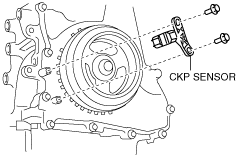
3. Disconnect the CKP sensor connector.
4. Remove the CKP sensor.
Installation
-
Caution
-
• When foreign material such as an iron chip is on the CKP sensor, it can cause abnormal output from the sensor because of flux turbulence and adversely affect the engine control. Be sure there is no foreign material on the CKP sensor when replacing.
1. Perform the following procedure so that cylinder No.1 is at TDC.
- (1) Disconnect the drive shaft (RH) from joint shaft, set the drive shaft (RH) out of the way. (ATX) (See DRIVE SHAFT REMOVAL/INSTALLATION.)
- (2) Remove the cylinder block lower blind plug and install the SST.
-
- (3) Rotate the crankshaft pulley clockwise until the crank weight contacts the SST so that cylinder No.1 is at TDC.
2. Fit the center of the CKP sensor with the fifth tooth (counting counterclockwise from the empty space A as shown in the figure) of the pulse wheel.
-
Caution
-
• If the line is not accurately drawn, ignition timing, fuel injection and other engine control systems will be adversely effected. Draw the straight line carefully using a straight edge.
3. Align the center line of the crankshaft position sensor and the line drawn in Step 2, then install the sensor.
4. Install the CKP sensor fitting bolts.
5. Remove the SST then install the cylinder block lower blind plug.