 |
am6zzw00006352
DRIVE SHAFT REMOVAL/INSTALLATION
id031300801900
1. Remove the aerodynamic under cover No. 2. (See AERODYNAMIC UNDER COVER NO.2 REMOVAL/INSTALLATION.)
2. Set the front mudguard out of the way. (See FRONT MUDGUARD REMOVAL/INSTALLATION.)
3. Remove the splash shield.
4. Drain the transaxle oil or ATF. (See TRANSAXLE OIL REPLACEMENT [G35M-R].) (See TRANSAXLE OIL REPLACEMENT [G66M-R].) (See TRANSAXLE OIL REPLACEMENT [A26M-R].) (See AUTOMATIC TRANSAXLE FLUID (ATF) REPLACEMENT [FS5A-EL].)
5. When working on the right side of the vehicle, disconnect the front auto leveling sensor link. (Vehicle with discharge headlight system) (See AUTO LEVELING SENSOR REMOVAL/INSTALLATION.)
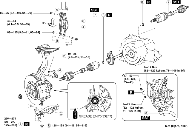
6. Remove in the order indicated in the table.
7. Install in the reverse order of removal.
am6zzw00006352
|
|
1
|
Locknut
|
|
2
|
Bolt (brake hose)
|
|
3
|
Tie-rod end ball joint
|
|
4
|
Nut (front stabilizer control link lower side)
|
|
5
|
Nut (lower arm)
|
|
6
|
Damper fork
|
|
7
|
Drive shaft
(See Drive Shaft Removal Note.)
|
|
8
|
Clip
(See Clip Installation Note.)
|
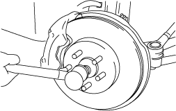
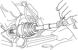
Drive Shaft Removal Note
1. Install a spare nut onto the drive shaft.
2. Tap the nut with a copper hammer and separate the drive shaft from the axle.
am3zzw00004394
|
3. Separate the drive shaft from the wheel hub.
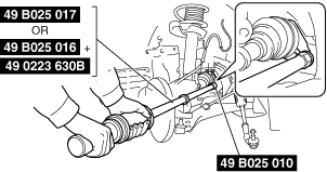
4. Separate the drive shaft (LH) from the transaxle by using the SSTs.
am6zzw00011758
|
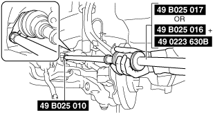
5. Disconnect the drive shaft (RH) from the joint shaft by using the SSTs.
am6zzw00004365
|
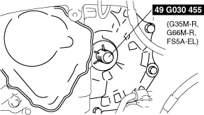
6. Install the SST to the transaxle after the drive shaft is removed.
am6zzw00009566
|
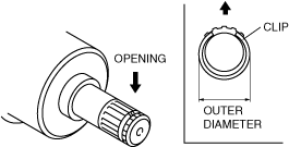
Clip Installation Note
1. Install a new drive shaft clip to the clip groove at the end of the drive shaft with the clip opening facing upward and the clip width within the specification.
am3zzw00004397
|
2. After installation, measure the outer diameter.
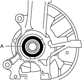
Drive Shaft Installation Note
Left side
1. Apply grease (D4Y0 33247) to the wheel bearing inner race and drive shaft contact surface (Area A in figure).
am6xuw00002787
|
2. Insert the drive shaft into the wheel hub.
3. Apply transaxle oil or ATF to the oil seal lip.
4. Install the drive shaft to the transaxle.
am3zzw00004398
|
5. After installation, pull the transaxle side outer ring forward to confirm that the drive shaft is securely held by the clip.
Right side
1. Install a new clip onto the joint shaft. (See JOINT SHAFT REMOVAL/INSTALLATION.)
2. Apply grease (D4Y0 33247) to the wheel bearing inner race and drive shaft contact surface (Area A in figure).
am6xuw00002789
|
3. Insert the drive shaft to the wheel hub.
4. Insert the drive shaft to the joint shaft.
5. After installation, pull the transaxle side outer ring forward to confirm that the drive shaft is securely held by the clip.