 |
am6zzw00006960
DTC C0051:2F/C0052:11/C0052:13/C0053:11/C0053:13/C0054:11/C0054:13/C0055:11/C0055:13 [BCM]
id0902f5415600
Description
Detection Condition
Possible Causes
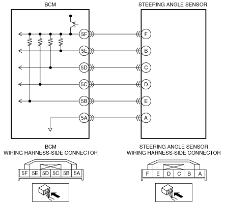
System Wiring Diagram
am6zzw00006960
|
Diagnostic Procedure
|
Step |
Inspection |
Action |
|
|---|---|---|---|
|
1
|
PERFORM DTC INSPECTION
• Clear the DTCs using the M-MDS.
(See CLEARING DTC [BCM].)
• Perform the BCM DTC inspection using the M-MDS.
(See DTC INSPECTION [BCM].)
• Are any of the following DTC present?
|
Yes
|
Go to the next step.
|
|
No
|
DTC troubleshooting completed.
|
||
|
2
|
INSPECT STEERING ANGLE SENSOR CONNECTOR CONDITION
• Switch the ignition to off.
• Disconnect the negative battery cable.
• Disconnect the steering angle sensor connector.
• Inspect the connector and terminals (corrosion, damage, pin disconnection).
• Is there any malfunction?
|
Yes
|
Repair or replace the connector or terminals, then go to Step 8.
|
|
No
|
Go to the next step.
|
||
|
3
|
INSPECT BCM CONNECTOR CONDITION
• Disconnect the BCM connector.
• Inspect the connector and terminals (corrosion, damage, pin disconnection).
• Is there any malfunction?
|
Yes
|
Repair or replace the connector or terminals, then go to Step 8.
|
|
No
|
C0051:2F/C0052:11/ C0053:11/C0054:11/C0055:11
• Go to the next step.
C0052:13/C0053:13/C0054:13/C0055:13
• Go to Step 6.
|
||
|
4
|
INSPECT STEERING ANGLE SENSOR CIRCUIT FOR SHORT TO GROUND
• Steering angle sensor and BCM connectors are disconnected.
• Inspect for continuity between the following terminals (wiring harness-side) and body ground:
• Is there continuity?
|
Yes
|
Repair or replace the wiring harness for a possible short to ground, then go to Step 8.
|
|
No
|
Go to the next step.
|
||
|
5
|
INSPECT STEERING ANGLE SENSOR CIRCUITS FOR SHORT TO EACH OTHER
• Steering angle sensor and BCM connectors are disconnected.
• Switch the ignition to off.
• Disconnect the negative battery cable.
• Inspect for continuity between steering angle sensor terminals A, B, C, D, E, and F (wiring harness-side).
• Is there continuity?
|
Yes
|
Repair or replace the wiring harness for a possible short to each other, then go to Step 8.
|
|
No
|
Go to the next step.
|
||
|
6
|
INSPECT STEERING ANGLE SENSOR CIRCUIT FOR OPEN CIRCUIT
• Steering angle sensor and BCM connectors are disconnected.
• Inspect for continuity between the following terminals (wiring harness-side):
• Is there continuity?
|
Yes
|
Go to the next step.
|
|
No
|
Repair or replace the wiring harness for a possible open circuit, then go to Step 8.
|
||
|
7
|
INSPECT STEERING ANGLE SENSOR
• Inspect the steering angle sensor.
• Is there any malfunction?
|
Yes
|
Replace the steering angle sensor, then go to the next step.
|
|
No
|
Go to the next step.
|
||
|
8
|
VERIFY TROUBLESHOOTING COMPLETED
• Make sure to reconnect all disconnected connectors.
• Reconnect the negative battery cable.
• Clear the DTCs using the M-MDS.
(See CLEARING DTC [BCM].)
• Perform the BCM DTC inspection using the M-MDS.
(See DTC INSPECTION [BCM].)
• Are any of the following DTC present?
|
Yes
|
Repeat the inspection from Step 1.
• If the malfunction recurs, replace the BCM.
Go to the next step.
|
|
No
|
Go to the next step.
|
||
|
9
|
VERIFY THAT NO OTHER DTCs ARE PRESENT
• Are any DTCs present?
|
Yes
|
Go to the applicable DTC inspection.
(See DTC TABLE [BCM].)
|
|
No
|
DTC troubleshooting completed.
|
||