|
1
|
INSPECT BCM POWER SUPPLY FUSES
• Are the BCM power supply fuses normal?
|
Yes
|
Go to the next step.
|
|
No
|
Install an appropriate amperage fuse.
|
|
2
|
INSPECT DOOR LATCH SWITCH INSTALLATION
• Are the door latch switches installed securely?
|
Yes
|
Go to the next step.
|
|
No
|
Install the door latch switches securely, then go back to Step 5 of keyless entry system preliminary inspection.
|
|
*3
|
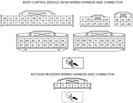
INSPECT IF MALFUNCTION IS IN WIRING HARNESS (NO CONTINUITY BETWEEN FUSE BLOCK AND BCM) OR ELSEWHERE
• Switch the ignition to ON.
• Measure the voltage at the following BCM terminals:
-
― IG1 signal (terminal 3AB, 4A)
― Power supply signal (terminal 2D, 2J, 4B, 4C)
• Is the voltage B+?
|
Yes
|
Go to the next step.
|
|
No
|
Repair the wiring harness between the fuse block and BCM, then go to Step 13.
|
|
*4
|
INSPECT IF MALFUNCTION IS IN WIRING HARNESS (SHORT TO POWER SUPPLY BETWEEN FUSE BLOCK AND BCM, OR BETWEEN BCM AND GROUND) OR ELSEWHERE
• Switch the ignition to off.
• Disconnect the BCM connector.
• Measure the voltage at the following BCM terminal (wiring harness-side):
-
― IG1 signal (terminal 3AB, 4A)
• Is the voltage B+?
|
Yes
|
Repair the malfunctioning wiring harness, then go to Step 13.
|
|
No
|
Go to the next step.
|
|
*5
|
INSPECT IF MALFUNCTION IS IN WIRING HARNESS (NO CONTINUITY BETWEEN BCM AND GROUND) OR ELSEWHERE
• Is there continuity between BCM terminal 1V, 2A and ground?
|
Yes
|
Go to the next step.
|
|
No
|
Repair the wiring harness between the BCM and ground, then go to Step 13.
|
|
6
|
INSPECT DOOR SWITCH SIGNAL
• Monitor following BCM (door switch) PID using the M-MDS.
-
― TR/LG_SW (Trunk lid/liftgate latch switch)
― DRSW_P (Passenger’s door latch switch)
― DRSW_D (Driver’s door switch)
― DRSW_LR (Rear door latch switch (LH))
― DRSW_RR (Rear door latch switch (RH))
• Are monitored PID values normal?
|
Yes
|
Go to the next step.
|
|
No
|
• Inspect for open or short circuit in wiring harness between BCM and suspected door latch/trunk lid (4SD)/liftgate (5HB) latch switch.
-
― If wiring harness is normal, inspect suspect door latch/trunk lid (4SD)/liftgate (5HB) latch switch.
― If wiring harness malfunction, repair or replace wiring harness, then go to Step 13.
|
|
7
|
INSPECT BCM OR WIRING HARNESS (BETWEEN BCM AND DOOR LATCH SWITCHES FOR CONTINUITY)
• Open all doors.
• Is there continuity between BCM terminals 8B, 8D, 8F, 8H and ground?
|
Yes
|
Replace the BCM and reprogram the transmitter ID code, then go to the next step.
|
|
No
|
Repair the wiring harness between the BCM and door latch switches, then go to the next step.
|
|
8
|
INSPECT POWER SUPPLY FUSE
• Is the keyless receiver power supply fuse normal?
|
Yes
|
Go to the next step.
|
|
No
|
Inspect and repair short to GND in wiring harness at keyless receiver power supply circuit install an appropriate amperage fuse, then go to step 13.
|
|
9
|
INSPECT IF MALFUNCTION IS IN WIRING HARNESS (NO CONTINUITY BETWEEN FUSE BLOCK AND KEYLESS RECEIVER) OR ELSEWHERE
• Switch the ignition to ON.
• Measure the voltage at the following keyless receiver terminal:
-
― Power supply signal (terminal A)
• Is the voltage B+?
|
Yes
|
Go to the next step.
|
|
No
|
Repair the wiring harness between the fuse block and keyless receiver, then go to Step 13.
|
|
10
|
INSPECT IF MALFUNCTION IS IN WIRING HARNESS (NO CONTINUITY BETWEEN KEYLESS RECEIVER AND GROUND) OR ELSEWHERE
• Is there continuity between keyless receiver terminal E and ground?
|
Yes
|
Go to the next step.
|
|
No
|
Repair the wiring harness between the keyless receiver and ground, then go to Step 13.
|
|
11
|
INSPECT IF MALFUNCTION IS IN WIRING HARNESS (NO CONTINUITY BETWEEN KEYLESS RECEIVER AND BCM) OR ELSEWHERE
• Switch the ignition to ON.
• Disconnect the keyless receiver connector and BCM connector.
• Is there continuity between the following terminals?
-
― 6J (BCM connector)—D (keyless receiver connector)
|
Yes
|
Go to the next step.
|
|
No
|
Repair the wiring harness between the keyless receiver and BCM, then go to Step 13.
|
|
12
|
INSPECT IF MALFUNCTION IS IN KEYLESS RECEIVER OR BCM
• Measure the signal wave pattern for BCM terminal 6J using an oscilloscope when the transmitter is operated with the key not inserted into the ignition key cylinder.
• Does the wave pattern change when the transmitter is operated?
-
Note
-
• Perform the oscilloscope setting using 0.5V/DIV (Y), 100ms/DIV (X), DC range.
|
Yes
|
Replace the BCM, then go to the next step.
|
|
No
|
Replace the keyless receiver, then go to the next step.
|
|
13
|
REINSPECT MALFUNCTION SYMPTOM AFTER REPAIR
• Does the keyless entry system operate properly?
|
Yes
|
Troubleshooting completed.
Explain repairs to the customer.
|
|
No
|
Reinspect the malfunction symptoms, then repeat from Step 1 if the malfunction recurs.
|