am6zzw00004325
|
REAR VEHICLE MONITORING RADAR AIMING
id092200486500
Introduction
am6zzw00004325
|
Radar aiming procedure
1. Remove any occupants and unload cargo from the cabin and trunk compartment so that the vehicle is in an unloaded condition.
2. Adjust the air pressure of each tire to the specified value.
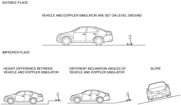
3. Park the vehicle on a level surface.
4. Verify that there are no obstructions or metal material in the radar emission area shown in the figure.
am6zzw00004326
|
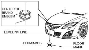
5. Adjust the commercially available plumb-bob so that it is aligned with the center of the brand emblem, determine the center position at the front of the vehicle, and mark the center position on the floor surface.
am6zzw00006234
|
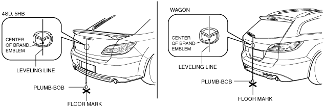
6. Adjust the plumb-bob so that it is aligned with the center of the brand emblem, determine the center position at the rear of the vehicle, and mark the center position on the floor surface.
am6zzw00006235
|
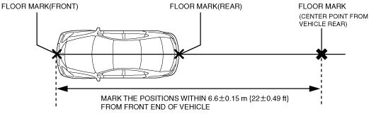
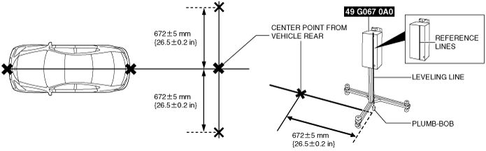
7. Position the leveling line over the marked positions at the front and rear of the vehicle, and then mark the position on the floor surface 6.6±0.15 m {22±0.49 ft} from the front end of the vehicle.
am6zzw00004237
|
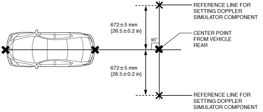
8. Mark the positions on the left and right which form right angles to the center position from the vehicle rear to a distance of 672± 5 mm {26.5±0.2 in}.
am6zzw00004327
|
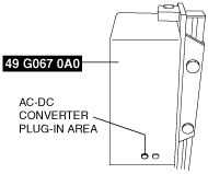
9. Insert the SST (AC-DC converter) into the side of the SST (Doppler simulator) and turn on the power.
am6zzw00004328
|
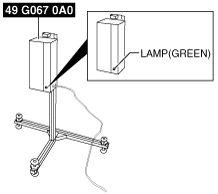
10. Verify that the green lamp on the SST (Doppler simulator) unit illuminates.
am6zzw00004238
|
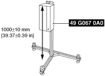
11. Adjust the SST (Doppler simulator) so that its height from the top surface to the floor is 1000±10 mm{39.37±0.39 in}.
am6zzw00005103
|
am6zzw00004239
|
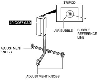
12. Level the SST (Doppler simulator) installation surface using the bubble level built into the SST (Doppler simulator).
am6zzw00004240
|
13. Adjust the adjustment knobs so that the air bubble is centered between the reference lines.
14. Drop the plumb-bob to the floor along the reference line printed on the SST (Doppler simulator) unit.
am6zzw00004241
|
15. Adjust the SST (Doppler simulator) position so that the end of the plumb-bob is aligned with the floor marking. Set SST (Doppler simulator) as parallel as possible to the axle direction.
am6zzw00004242
|
am6zzw00004698
|
16. After the end of the plumb-bob is aligned with the marking, remove the plumb-bob.
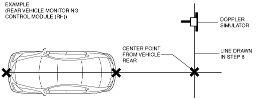
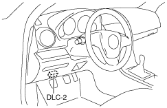
17. Use the M-MDS to perform the rear vehicle monitoring radar aiming according to the instructions on the screen.
18. Connect the M-MDS (IDS) to the DLC-2.
am6zzw00000768
|
19. After the vehicle is identified, select “Electrical”, then “RVM Aiming” from the initial screen of the IDS.
20. Perform the procedure according to the directions on the screen.
21. Verify the M-MDS display.
|
Step |
Inspection |
Action |
|
|---|---|---|---|
|
1
|
DOPPLER SIMULATOR POSITION SET VERIFICATION
• Verify if the Doppler simulator is set in the correct position.
• Is the Doppler simulator set in the correct position?
|
Yes
|
Go to the next step.
|
|
No
|
Set the Doppler simulator in the correct position and perform the rear vehicle monitoring radar aiming.
|
||
|
2
|
DO REAR MONITORING RADAR AIMING AGAIN
• Perform the rear vehicle monitoring radar aiming.
• M-MDS operations (Step 19-20) for the rear vehicle monitoring radar aiming is repeated 2 or 3 times before “Procedure successful.” is displayed.
• Is “Procedure successful.” displayed?
|
Yes
|
The rear vehicle monitoring radar aiming is completed.
|
|
No
|
Go to the next step.
|
||
|
3
|
VERIFY EFFECT OF REAR BUMPER
• Remove the rear bumper.
• Perform the rear vehicle monitoring radar aiming procedure.
• M-MDS operations (Step 19-20) for the rear vehicle monitoring radar aiming is repeated 2 or 3 times before “Procedure successful.” is displayed.
• Is “Procedure successful.” displayed?
|
Yes
|
Replace the rear bumper.
|
|
No
|
Go to the next step.
|
||
|
4
|
VERIFICATION OF REAR VEHICLE MONITORING CONTROL MODULE OR REAR VEHICLE MONITORING BRACKET MIS-INSTALLATION, OR DISTORTION ON INSTALLATION SURFACE
• Verify whether a rear vehicle monitoring control module or rear vehicle monitoring bracket has been mis-installed, or if there is distortion on the vehicle installation surface.
• Is there a mis-installation or distortion to the installation surface?
|
Yes
|
Repair or replace the malfunctioning part and perform the rear vehicle monitoring radar aiming procedure.
|
|
No
|
Replace the rear vehicle monitoring control module and perform the rear vehicle monitoring radar aiming procedure.
|
||