 |
am6zzw00017889
DTC P2503:00 [PCM (SKYACTIV-D 2.2)]
id0102j5709600
Details On DTCs (Without i-ELOOP)
|
System malfunction location |
Generator system: Voltage generated by generator is low |
|
|---|---|---|
|
Detection condition
|
Determination condition
|
• A condition continues for a specified period of time in which the generator target output current calculated by the PCM is 20 A or more and the generator output voltage is 8.5 V or less.
|
|
Preconditions
|
• Engine is running
|
|
|
determination period
|
• 5 s
|
|
|
Drive cycle
|
• 1
|
|
|
Self-test type
|
• CMDTC self test
|
|
|
Sensor/unit used
|
• PCM
• Generator
|
|
|
Fail-safe
|
• Inhibits the i-stop control.
|
|
|
Vehicle status when DTCs are output
|
• i-stop warning light (amber) flashes
• A warning message is displayed on the LCD in the instrument cluster.
|
|
|
Possible cause
|
• Poor connection of the following parts:
• Connector or terminal malfunction of the following parts:
• Malfunction in the following fuses:
• Short to ground in wiring harness between the following terminals:
• Open circuit in wiring harness between the following terminals:
• Generator drive belt shear, deviation, or wear
• Malfunction in generator
• PCM malfunction
|
|
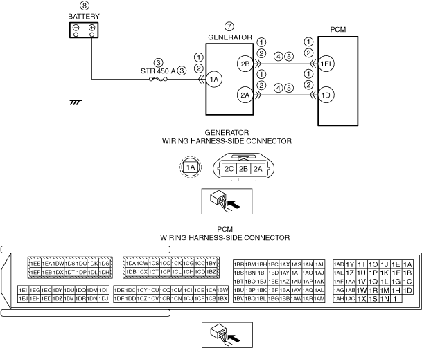
System Wiring Diagram (Without i-ELOOP)
am6zzw00017889
|
Function Explanation (DTC Detection Outline) (Without i-ELOOP)
Repeatability Verification Procedure (Without i-ELOOP)
PID Item/Simulation Item Used in Diagnosis
Function Inspection Using M-MDS (Without i-ELOOP)
|
Step |
Inspection |
Results |
Action |
|---|---|---|---|
|
1
|
PURPOSE: RECORD VEHICLE STATUS AT TIME OF DTC DETECTION TO UTILIZE WITH REPEATABILITY VERIFICATION
• Record the freeze frame data/snap shot data.
|
—
|
Go to Troubleshooting Diagnostic Procedure to perform the procedure from step 1.
|
Troubleshooting Diagnostic Procedure (Without i-ELOOP)
|
Step |
Inspection |
Results |
Action |
|---|---|---|---|
|
1
|
PURPOSE: VERIFY IF POOR CONNECTION OF EACH PART AFFECTS DIAGNOSTIC RESULTS
• Switch the ignition OFF.
• Inspect the connection condition (part installation condition, connector connection condition) for the following parts:
• Is the connection condition (part installation condition, connector connection condition) for each part normal?
|
Yes
|
Go to the next step.
|
|
No
|
Connect each part or the connector correctly, then go to the next step.
|
||
|
2
|
PURPOSE: VERIFY IF CONNECTOR DAMAGE OF EACH PART AFFECTS DIAGNOSTIC RESULTS
• Disconnect the connectors of the following parts:
• Inspect the connector engagement and connection condition, and inspect the terminals for damage, deformation, corrosion, or disconnection.
• Is the connector normal?
|
Yes
|
Go to the next step.
|
|
No
|
Repair or replace the connector, then go to the next step.
|
||
|
3
|
PURPOSE: INSPECT FOR MALFUNCTION DUE TO BAD FUSE
• Remove the STR 450 A fuse.
• Inspect the STR 450 A fuse.
• Is the STR 450 A fuse normal?
|
Yes
|
Install all the removed fuses, then go to the next step.
|
|
No
|
If the fuse is blown:
• Refer to the wiring diagram and verify if there is a common connector between the battery positive terminal and generator terminal 1A.
If there is a common connector:
If there is no common connector:
If the fuse is damaged:
• Replace the damaged fuse.
Go to the next step.
|
||
|
4
|
PURPOSE: VERIFY IF SHORT TO GROUND IN EACH WIRING HARNESS AFFECTS DIAGNOSTIC RESULTS
• Verify that the generator and the PCM connectors are disconnected.
• Disconnect the battery connector.
• Inspect for continuity between the following terminals (vehicle wiring harness side) and ground.
• Is there continuity?
|
Yes
|
Refer to the wiring diagram and verify if there is a common connector between the following terminals.
• Generator terminal 2B and PCM terminal 1BR
• Generator terminal 2A and PCM terminal 1Z
If there is a common connector:
If there is no common connector:
Go to the next step.
|
|
No
|
Go to the next step.
|
||
|
5
|
PURPOSE: VERIFY IF OPEN CIRCUIT IN EACH WIRING HARNESS AFFECTS DIAGNOSTIC RESULTS
• Verify that the battery and generator connectors, and the PCM connector are disconnected.
• Verify that the IG1 relay No.2 is removed.
• Inspect between the following terminals (vehicle wiring harness side) for continuity.
• Is there continuity?
|
Yes
|
Go to Step 8.
|
|
No
|
Refer to the wiring diagram and verify if there is a common connector between the following terminals.
• Generator terminal 2B and PCM terminal 1EI
• Generator terminal 2A and PCM terminal 1D
If there is a common connector:
If there is no common connector:
Go to the next step.
|
||
|
6
|
PURPOSE: VERIFY IF DIAGNOSTIC RESULT IS AFFECTED BY MALFUNCTION RELATED TO GENERATOR DRIVE BELT
• Inspect the generator drive belt.
• Is the indicator mark on the drive belt auto tensioner within the normal range?
|
Yes
|
Go to the next step.
|
|
No
|
Replace the generator drive belt, then go to the next step.
|
||
|
7
|
PURPOSE: DETERMINE INTEGRITY OF GENERATOR
• Inspect the generator.
• Is the generator normal?
|
Yes
|
Go to the next step.
|
|
No
|
Replace the generator, then go to the next step.
|
||
|
8
|
PURPOSE: VERIFY BATTERY CHARGE CONDITION
• Inspect the battery.
(See BATTERY INSPECTION.)
|
—
|
Follow the inspection instructions, then go to the next step.
|
|
9
|
PURPOSE: VERIFICATION OF VEHICLE REPAIR COMPLETION
• Reconnect all disconnected connectors and hoses.
• Refer to the [MEMORY CLEARING PROCEDURE] and clear the DTC.
• Implement the repeatability verification procedure.
• Display the DTCs using the M-MDS.
• Is DTC P2503:00 displayed?
|
Yes
|
Repeat the inspection from Step 1.
• If the malfunction recurs, replace the PCM, then go to the next step.
|
|
No
|
Go to the next step.
|
||
|
10
|
PURPOSE: VERIFY IF THERE IS ANY OTHER MALFUNCTION
• Has any other DTC or pending code been stored?
|
Yes
|
Repair the malfunctioning location according to the applicable DTC troubleshooting.
|
|
No
|
DTC troubleshooting completed.
|
Details On DTCs (With i-ELOOP)
|
DESCRIPTION |
Generator system: Voltage generated by generator is low |
|
|---|---|---|
|
DETECTION CONDITION
|
Determination conditions
|
• Any one of the following conditions is met:
|
|
Preconditions
|
• All of the following conditions are met:
|
|
|
Period of abnormality
|
• 5 s period
|
|
|
Drive cycle
|
• 1
|
|
|
Self test type
|
• CMDTC self test
|
|
|
Sensor used
|
• PCM, Generator
|
|
|
FAIL-SAFE FUNCTION
|
• Inhibits engine-stop by operating the i-stop function.
|
|
|
VEHICLE STATUS WHEN DTCs ARE OUTPUT
|
• Flashes i-stop warning light (amber).
• A warning message is displayed on the center display. (With center display)
• A warning message is displayed on the LCD in the instrument cluster. (Type A instrument cluster)
• Illuminates charging system warning light.
• The following vehicle conditions differ depending on the type of malfunction
|
|
|
POSSIBLE CAUSE
|
• Poor connection of the following parts:
• Connector or terminal malfunction of the following parts:
• MAIN 200 A fuse malfunction
• C/U IG1 15 A fuse malfunction
• Short to ground in wiring harness between the following terminals:
• Open circuit in wiring harness between the following terminals:
• Drive belt exceeds limit
• Generator malfunction
• PCM malfunction
|
|
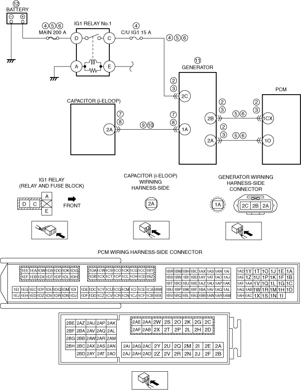
System Wiring Diagram (With i-ELOOP)
am6zzw00017653
|
Function Explanation (DTC Detection Outline) (With i-ELOOP)
Repeatability Verification Procedure (With i-ELOOP)
PID Item/Simulation Item Used In Diagnosis (With i-ELOOP)
Function Inspection Using M-MDS (With i-ELOOP)
|
STEP |
INSPECTION |
RESULTS |
ACTION |
|---|---|---|---|
|
1
|
PURPOSE: VERIFY RELATED SERVICE INFORMATION AVAILABILITY
• Verify related Service Information availability.
• Is any related Service Information available?
|
Yes
|
Perform repair or diagnosis according to the available Service Information.
• If the vehicle is not repaired, go to the next step.
|
|
No
|
Go to the next step.
|
||
|
2
|
PURPOSE: VERIFY THE PRE-CHARGE MODE CONDITION AND DETERMINE THE MALFUNCTION LOCATION.
• Start the engine.
• Is “i-ELOOP charging Please don’t Drive This will take less than 3 min” displayed in the LCD?
|
Yes
|
Go to the next step.
|
|
No
|
Go to Troubleshooting Diagnostic Procedure to perform the procedure from step 1.
|
||
|
3
|
PURPOSE: VERIFY IF GENERATOR OUTPUT IS AFFECTED BY DTC OCCURRING FROM DC-DC CONVERTER (i-ELOOP) RELATED PART
• Switch the ignition to off, then to ON (engine off or on).
• Perform the DC-DC converter (i-ELOOP) DTC inspection using the M-MDS.
• Are any DTCs present?
|
Yes
|
Repair or replace the malfunctioning part according to the applicable DTC troubleshooting.
Go to the next step.
|
|
No
|
Go to the next step.
|
||
|
4
|
PURPOSE: VERIFY DTC
• Retrieve the PCM DTCs using the M-MDS.
• Are any DTCs present?
|
Yes
|
Go to the applicable DTC inspection.
Go to Troubleshooting Diagnostic Procedure to perform the procedure from step 1.
|
|
No
|
Go to Troubleshooting Diagnostic Procedure to perform the procedure from step 1.
|
Troubleshooting Diagnostic Procedure (With i-ELOOP)
|
STEP |
INSPECTION |
RESULTS |
ACTION |
|---|---|---|---|
|
1
|
PURPOSE: DETERMINE THE MALFUNCTION CAUSE BY VERIFYING THE OUTPUT VOLTAGE OF GENERATOR TERMINAL 1A.
• Start the engine.
• Measure the voltage at the generator terminal 1A.
• Is the voltage approx. 14.5 V?
|
Yes
|
Go to the next step.
|
|
No
|
If the voltage is 0 V:
• Go to Step 7.
If the voltage is except for 0 V:
• Go to the next step.
|
||
|
2
|
PURPOSE: VERIFY IF POOR CONNECTION OF EACH PART AFFECTS DIAGNOSTIC RESULTS
• Switch the ignition to off.
• Disconnect the service plug.
• Inspect the connection condition (part installation condition, connector connection condition) for the following parts:
• Is the connection condition (part installation condition, connector connection condition) for each part normal?
|
Yes
|
Go to the next step.
|
|
No
|
Connect each part or the connector correctly, then go to the next step.
|
||
|
3
|
PURPOSE: VERIFY IF CONNECTOR DAMAGE OF EACH PART AFFECTS DIAGNOSTIC RESULTS
• Disconnect the connector of the following parts.
• Inspect for poor connection (such as damaged/pulled-out pins, corrosion).
• Is there any malfunction?
|
Yes
|
Repair or replace the connector and/or terminals, then go to the next step.
|
|
No
|
Go to the next step.
|
||
|
4
|
PURPOSE: INSPECT FUSE
• Remove the MAIN 200 A fuse and C/U IG1 15 A fuse.
• Inspect the MAIN 200 A fuse and C/U IG1 15 A fuse.
• Are there any malfunction?
|
Yes
|
If the fuse is burnt out:
• Refer to the wiring diagram and verify whether or not there is a common connector between the following terminals:
If there is a common connector:
― Determine the malfunctioning part by inspecting the common connector and the terminal for corrosion, damage, or pin disconnection, and the common wiring harness for a short to ground.
― Repair or replace the malfunctioning part.
If there is no common connector:
― Repair or replace the wiring harness which has a short to ground.
― Replace the malfunctioning fuse.
If the fuse is damaged:
• Replace the fuse.
Go to Step 9.
|
|
No
|
Reinstall the MAIN 200 A fuse and C/U IG1 15 A fuse, then go to the next step.
|
||
|
5
|
PURPOSE: VERIFY IF SHORT TO GROUND IN EACH WIRING HARNESS AFFECTS DIAGNOSTIC RESULTS
• Verify that the generator and PCM connectors are disconnected.
• Disconnect the battery positive terminal.
• Remove the IG1 relay No.2.
• Inspect for continuity between the following terminals (wiring harness-side) and body ground:
• Is there continuity?
|
Yes
|
Refer to the wiring diagram and verify whether or not there is a common connector between the following terminals:
• Battery positive terminal—IG1 relay No.2 terminal D
• IG1 relay No.2 terminal C—Generator terminal 2C
• Generator terminal 2B—PCM terminal 2W
• Generator terminal 2A—PCM terminal 1O
If there is a common connector:
• Determine the malfunctioning part by inspecting the common connector and the terminal for corrosion, damage, or pin disconnection, and the common wiring
• Repair or replace the malfunctioning part.
If there is no common connector:
• Repair or replace the wiring harness which has a short to ground.
Go to the next step.
|
|
No
|
Go to the next step.
|
||
|
6
|
PURPOSE: VERIFY IF OPEN CIRCUIT IN EACH WIRING HARNESS AFFECTS DIAGNOSTIC RESULTS
• Verify that the generator and PCM connectors are disconnected.
• Verify that the battery positive terminal is disconnected.
• Verify that the IG1 relay No.2 is removed.
• Inspect for continuity between the following terminals (wiring harness-side):
• Is there continuity?
|
Yes
|
Go to Step 13.
|
|
No
|
Refer to the wiring diagram and verify whether or not there is a common connector between the following terminals:
• Battery positive terminal—IG1 relay No.2 terminal D
• IG1 relay No.2 terminal C—Generator terminal 2C
• Generator terminal 2B—PCM terminal 2W
• Generator terminal 2A—PCM terminal 1O
If there is a common connector:
• Determine the malfunctioning part by inspecting the common connector and the terminal for corrosion, damage, or pin disconnection, and the common wiring
• Repair or replace the malfunctioning part.
If there is no common connector:
• Repair or replace the wiring harness which has a short to ground.
Go to step 11.
|
||
|
7
|
PURPOSE: VERIFY IF POOR CONNECTION OF EACH PART AFFECTS DIAGNOSTIC RESULTS
• Switch the ignition to off.
• Disconnect the service plug.
• Inspect the connection condition (part installation condition, connector connection condition) for the following parts:
• Is the connection condition (part installation condition, connector connection condition) for each part normal?
|
Yes
|
Go to the next step.
|
|
No
|
Connect each part or the connector correctly, then go to the next step.
|
||
|
8
|
PURPOSE: VERIFY IF CONNECTOR DAMAGE OF EACH PART AFFECTS DIAGNOSTIC RESULTS
• Disconnect the connector of the following parts.
• Inspect for poor connection (such as damaged/pulled-out pins, corrosion).
• Is there any malfunction?
|
Yes
|
Repair or replace the connector and/or terminals, then go to the next step.
|
|
No
|
Go to the next step.
|
||
|
9
|
PURPOSE: VERIFY IF SHORT TO GROUND IN GENERATOR CHARGE/DISCHARGE CIRCUIT AFFECTS DIAGNOSTIC RESULTS
• Verify that the battery, generator and capacitor (i-ELOOP) connectors are disconnected.
• Inspect for continuity between generator terminal 1A (wiring harness-side) and body ground.
• Is there continuity?
|
Yes
|
Refer to the wiring diagram and verify whether or not there is a common connector between capacitor (i-ELOOP) terminal 2A and generator terminal 1A.
If there is a common connector:
• Determine the malfunctioning part by inspecting the common connector and the terminal for corrosion, damage, or pin disconnection, and the common wiring
• Repair or replace the malfunctioning part.
If there is no common connector:
• Repair or replace the wiring harness which has a short to ground.
Go to the next step.
|
|
No
|
Go to the next step.
|
||
|
10
|
PURPOSE: VERIFY IF OPEN CIRCUIT IN GENERATOR CHARGE/DISCHARGE CIRCUIT AFFECTS DIAGNOSTIC RESULTS
• Verify that the battery, generator and capacitor (i-ELOOP) connectors are disconnected.
• Inspect for continuity between capacitor (i-ELOOP) terminal 2A (wiring harness-side) and generator terminal 1A (wiring harness-side).
• Is there continuity?
|
Yes
|
Go to the next step.
|
|
No
|
Refer to the wiring diagram and verify whether or not there is a common connector between capacitor (i-ELOOP) terminal 2A and generator terminal 1A.
If there is a common connector:
• Determine the malfunctioning part by inspecting the common connector and the terminal for corrosion, damage, or pin disconnection, and the common wiring harness for an open circuit.
• Repair or replace the malfunctioning part.
If there is no common connector:
• Repair or replace the wiring harness which has an open circuit.
Go to the next step.
|
||
|
11
|
PURPOSE: VERIFY IF MALFUNCTION RELATED TO GENERATOR DRIVE BELT AFFECTS DIAGNOSTIC RESULTS
• Inspect the generator drive belt.
• Is the indicator mark on the drive belt auto tensioner within the normal range?
|
Yes
|
Go to the next step.
|
|
No
|
Replace the generator drive belt, then go to Step 9.
|
||
|
12
|
PURPOSE: DETERMINE INTEGRITY OF GENERATOR
• Inspect the generator.
• Is there any malfunction?
|
Yes
|
Replace the generator, then go to the next step.
|
|
No
|
Go to the next step.
|
||
|
13
|
PURPOSE: DETERMINE INTEGRITY OF BATTERY
• Inspect the battery.
(See BATTERY INSPECTION)
|
—
|
Follow the inspection instructions, then go to the next step.
|
|
14
|
PURPOSE: VERIFICATION OF VEHICLE REPAIR COMPLETION
• Always reconnect all disconnected connectors.
• Reconnect the service plug.
• Clear the DTC from the PCM memory using the M-MDS.
• Implement the repeatability verification procedure.
• Perform the DTC Reading Procedure.
• Is the same DTC present?
|
Yes
|
Repeat the inspection from Step 1.
• If the malfunction recurs, replace the PCM.
Go to the next step.
|
|
No
|
Go to the next step.
|
||
|
15
|
PURPOSE: VERIFY IF THERE IS ANY OTHER MALFUNCTION
• Is any other DTC or pending code stored?
|
Yes
|
Go to the applicable DTC inspection.
|
|
No
|
DTC troubleshooting completed.
|