 |
am6zzw00017890
DTC P2504:00 [PCM (SKYACTIV-D 2.2)]
id0102j5709700
Details On DTCs (Without i-ELOOP)
|
System malfunction location |
Generator system: Voltage generated by generator is high |
|
|---|---|---|
|
Detection condition
|
Determination condition
|
• A specified period of time continues under the condition that the generator power generation voltage is 18.5 V or more or the battery voltage is 16 V or more.
|
|
Preconditions
|
• Engine is running
|
|
|
determination period
|
• 5 s
|
|
|
Drive cycle
|
• 1
|
|
|
Self-test type
|
• CMDTC self test
|
|
|
Sensor/unit used
|
• PCM
• Generator
|
|
|
Fail-safe
|
• Inhibits engine-stop by i-stop control.
|
|
|
Vehicle status when DTCs are output
|
• i-stop warning light (amber) flashes
• Displays a message related to a charge system malfunction in the display.
|
|
|
Possible cause
|
• Poor connection of the following parts:
• Connector or terminal malfunction of the following parts:
• Short to power supply in wiring harness between the following terminals
• Battery malfunction
• Malfunction in generator
• PCM malfunction
|
|
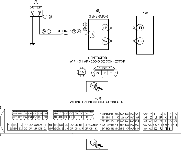
System Wiring Diagram (Without i-ELOOP)
am6zzw00017890
|
Function Explanation (DTC Detection Outline) (Without i-ELOOP)
Repeatability Verification Procedure (Without i-ELOOP)
PID Item/Simulation Item Used in Diagnosis (Without i-ELOOP)
Function Inspection Using M-MDS (Without i-ELOOP)
|
Step |
Inspection |
Results |
Action |
|---|---|---|---|
|
1
|
PURPOSE: RECORD VEHICLE STATUS AT TIME OF DTC DETECTION TO UTILIZE WITH REPEATABILITY VERIFICATION
• Record the freeze frame data/snap shot data.
|
—
|
Go to Troubleshooting Diagnostic Procedure to perform the procedure from step 1.
|
Troubleshooting Diagnostic Procedure (Without i-ELOOP)
|
Step |
Inspection |
Results |
Action |
|---|---|---|---|
|
1
|
PURPOSE: VERIFY IF POOR CONNECTION OF EACH PART AFFECTS DIAGNOSTIC RESULTS
• Switch the ignition OFF.
• Inspect the connection condition (part installation condition, connector connection condition) for the following parts:
• Is the connection condition (part installation condition, connector connection condition) for each part normal?
|
Yes
|
Go to the next step.
|
|
No
|
Connect each part or the connector correctly, then go to the next step.
|
||
|
2
|
PURPOSE: VERIFY IF CONNECTOR DAMAGE OF EACH PART AFFECTS DIAGNOSTIC RESULTS
• Disconnect the connectors of the following parts:
• Inspect the connector engagement and connection condition, and inspect the terminals for damage, deformation, corrosion, or disconnection.
• Is the connector normal?
|
Yes
|
Go to the next step.
|
|
No
|
Repair or replace the connector, then go to the next step.
|
||
|
3
|
PURPOSE: VERIFY IF SHORT TO POWER SUPPLY IN EACH WIRING HARNESS AFFECTS DIAGNOSTIC RESULTS
• Verify that the battery, generator connector, and the PCM connector are disconnected.
• Switch the ignition ON (engine off).
• Measure the voltage at the following terminals (vehicle wiring harness side).
• Is the voltage 0 V?
|
Yes
|
Go to the next step.
|
|
No
|
Refer to the wiring diagram and verify if there is a common connector between the following terminals.
• Battery positive terminal and generator terminal 1A
If there is a common connector:
• Inspect the common connector and terminals for corrosion, damage, or disconnection and the common wiring harnesses for short to power supply to determine the malfunctioning location.
• Repair or replace the malfunctioning location.
If there is no common connector:
• Repair or replace the wiring harness which is shorted to the power supply.
Go to the next step.
|
||
|
4
|
PURPOSE: VERIFY IF OPEN CIRCUIT IN GENERATOR CHARGE/DISCHARGE CIRCUIT AFFECTS DIAGNOSTIC RESULTS
• Verify that the battery connector, PCM connector, and the generator connector are disconnected.
• Switch the ignition OFF.
• Inspect wiring harness between the positive battery terminal and generator terminal 1A (vehicle wiring harness side).
• Is there continuity?
|
Yes
|
Go to the next step.
|
|
No
|
Refer to the wiring diagram and verify if there is a common connector between the battery positive terminal and generator terminal 1A.
If there is a common connector:
• Inspect the common connector and terminals for corrosion, damage, or disconnection and the common wiring harnesses for an open circuit to determine the malfunctioning location.
• Repair or replace the malfunctioning location.
If there is no common connector:
• Repair or replace the wiring harness which has an open circuit.
Go to the next step.
|
||
|
5
|
PURPOSE: VERIFY IF THERE IS MALFUNCTION CAUSED BY TEMPERATURE INCREASE AROUND GENERATOR
• Inspect the area around the generator.
• Is there a malfunction caused by a temperature increase around the generator?
|
Yes
|
Eliminate the abnormality around the generator, then go to the next step.
|
|
No
|
Go to the next step.
|
||
|
6
|
PURPOSE: DETERMINE INTEGRITY OF GENERATOR
• Inspect the generator.
• Is the generator normal?
|
Yes
|
Go to the next step.
|
|
No
|
Replace the generator, then go to the next step.
|
||
|
7
|
PURPOSE: VERIFY BATTERY CONDITION
• Inspect the battery.
(See BATTERY INSPECTION.)
|
—
|
Follow the inspection instructions, then go to the next step.
|
|
8
|
PURPOSE: VERIFICATION OF VEHICLE REPAIR COMPLETION
• Reconnect all disconnected connectors and hoses.
• Refer to the [MEMORY CLEARING PROCEDURE] and clear the DTC.
• Implement the repeatability verification procedure.
• Display the DTCs using the M-MDS.
• Is DTC P2504:00 displayed?
|
Yes
|
Repeat the inspection from Step 1.
• If the malfunction recurs, replace the PCM, then go to the next step.
|
|
No
|
Go to the next step.
|
||
|
9
|
PURPOSE: VERIFY IF THERE IS ANY OTHER MALFUNCTION
• Has any other DTC or pending code been stored?
|
Yes
|
Repair the malfunctioning location according to the applicable DTC troubleshooting.
|
|
No
|
DTC troubleshooting completed.
|
Details On DTCs (With i-ELOOP)
|
DESCRIPTION |
Generator system: Voltage generated by generator is high |
|
|---|---|---|
|
DETECTION CONDITION
|
Determination conditions
|
• Any one of the following conditions is met:
|
|
Preconditions
|
• While engine is running
|
|
|
Period of abnormality
|
• 5 s period
|
|
|
Drive cycle
|
• 1
|
|
|
Self test type
|
• CMDTC self test
|
|
|
Sensor used
|
• PCM
|
|
|
FAIL-SAFE FUNCTION
|
• Inhibits engine-stop by operating the i-stop function.
• The PCM outputs a non-power generation demand to the generator and then demands the generator to go into default mode (14.5 V constant voltage power generation). If the temperature of the generator exceeds the specified value, the generator itself stops power generation. But, if the internal circuit of the generator is malfunctioning, the generator may not accept the demand from the PCM.
|
|
|
VEHICLE STATUS WHEN DTCs ARE OUTPUT
|
• Flashes i-stop warning light (amber).
• A warning message is displayed on the center display. (With center display)
• A warning message is displayed on the LCD in the instrument cluster. (Type A instrument cluster)
• Illuminates charging system warning light.
• The following vehicle conditions differ depending on the type of malfunction.
|
|
|
POSSIBLE CAUSE
|
• Poor connection of the following parts:
• Connector or terminal malfunction of the following parts:
• Short to power supply in wiring harness between the following terminals:
• Open circuit in wiring harness between capacitor (i-ELOOP) terminal 2A—Generator terminal 1A
• Battery malfunction
• Capacitor (i-ELOOP) malfunction
• DC-DC converter (i-ELOOP) malfunction
• Generator malfunction
• PCM malfunction
|
|
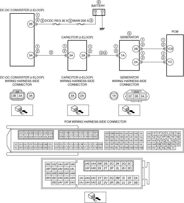
System Wiring Diagram (With i-ELOOP)
am6zzw00017891
|
Function Explanation (DTC Detection Outline) (With i-ELOOP)
Repeatability Verification Procedure (With i-ELOOP)
PID Item/Simulation Item Used In Diagnosis (With i-ELOOP)
Function Inspection Using M-MDS (With i-ELOOP)
|
STEP |
INSPECTION |
RESULTS |
ACTION |
|---|---|---|---|
|
1
|
PURPOSE: VERIFY RELATED SERVICE INFORMATION AVAILABILITY
• Verify related Service Information availability.
• Is any related Service Information available?
|
Yes
|
Perform repair or diagnosis according to the available Service Information.
• If the vehicle is not repaired, go to the next step.
|
|
No
|
Go to the next step.
|
||
|
2
|
PURPOSE: VERIFY IF GENERATOR OUTPUT IS AFFECTED BY DTC OCCURRING FROM DC-DC CONVERTER (i-ELOOP) RELATED PART
• Switch the ignition to off, then to ON (engine off or on).
• Perform the DC-DC converter (i-ELOOP) DTC inspection using the M-MDS.
• Are any DTCs present?
|
Yes
|
Repair or replace the malfunctioning part according to the applicable DTC troubleshooting.
|
|
No
|
Go to the next step.
|
||
|
3
|
PURPOSE: VERIFY DTC
• Retrieve the PCM DTCs using the M-MDS.
• Are any DTCs present?
|
Yes
|
Go to the applicable DTC inspection.
Go to Troubleshooting Diagnostic Procedure to perform the procedure from step 1.
|
|
No
|
Go to Troubleshooting Diagnostic Procedure to perform the procedure from step 1.
|
Troubleshooting Diagnostic Procedure (With i-ELOOP)
|
STEP |
INSPECTION |
RESULTS |
ACTION |
|---|---|---|---|
|
1
|
PURPOSE: VERIFY IF POOR CONNECTION OF EACH PART AFFECTS DIAGNOSTIC RESULTS
• Switch the ignition to off.
• Disconnect the service plug.
• Inspect the connection condition (part installation condition, connector connection condition) for the following parts:
• Is the connection condition (part installation condition, connector connection condition) for each part normal?
|
Yes
|
Go to the next step.
|
|
No
|
Connect each part or the connector correctly, then go to the next step.
|
||
|
2
|
PURPOSE: VERIFY IF CONNECTOR DAMAGE OF EACH PART AFFECTS DIAGNOSTIC RESULTS
• Disconnect the connector of the following parts.
• Inspect for poor connection (such as damaged/pulled-out pins, corrosion).
• Is there any malfunction?
|
Yes
|
Repair or replace the connector and/or terminals, then go to next step.
|
|
No
|
Go to the next step.
|
||
|
3
|
PURPOSE: VERIFY IF SHORT TO POWER SUPPLY IN EACH WIRING HARNESS AFFECTS DIAGNOSTIC RESULTS
• Verify that the generator, PCM, capacitor (i-ELOOP), and DC-DC converter (i-ELOOP) connectors are disconnected.
• Switch the ignition ON (engine off).
• Measure the voltage at the following terminals (wiring harness-side):
• Is the voltage 0 V?
|
Yes
|
Go to the next step.
|
|
No
|
Refer to the wiring diagram and verify whether or not there is a common connector between the following terminals:
• Battery positive terminal-DC-DC converter (i-ELOOP) terminal 2B
• DC-DC converter (i-ELOOP) terminal 3A—Capacitor (i-ELOOP) terminal 3A
• Capacitor (i-ELOOP) terminal 2A—Generator terminal 1A
If there is a common connector:
• Determine the malfunctioning part by inspecting the common connector and the terminal for corrosion, damage, or pin disconnection, and the common wiring harness for a short to power supply.
• Repair or replace the malfunctioning part.
If there is no common connector:
• Repair or replace the wiring harness which has a short to power supply.
Go to the next step.
|
||
|
4
|
PURPOSE: VERIFY IF OPEN CIRCUIT IN GENERATOR CHARGE/DISCHARGE CIRCUIT AFFECTS DIAGNOSTIC RESULTS
• Verify that the battery, generator and capacitor (i-ELOOP) connectors are disconnected.
• Inspect for continuity between capacitor (i-ELOOP) terminal 2A (wiring harness-side) and generator terminal 1A (wiring harness-side).
• Is there continuity?
|
Yes
|
Go to the next step.
|
|
No
|
Refer to the wiring diagram and verify whether or not there is a common connector between capacitor (i-ELOOP) terminal 2A and generator terminal 1A.
If there is a common connector:
• Determine the malfunctioning part by inspecting the common connector and the terminal for corrosion, damage, or pin disconnection, and the common wiring harness for an open circuit.
• Repair or replace the malfunctioning part.
If there is no common connector:
• Repair or replace the wiring harness which has an open circuit.
Go to the next step.
|
||
|
5
|
PURPOSE: DETERMINE INTEGRITY OF GENERATOR
• Inspect the generator.
• Is there any malfunction?
|
Yes
|
Replace the generator, then go to the next step.
|
|
No
|
Go to the next step.
|
||
|
6
|
PURPOSE: DETERMINE INTEGRITY OF BATTERY
• Inspect the battery.
(See BATTERY INSPECTION)
|
-
|
Follow the inspection instructions, then go to the next step.
|
|
7
|
PURPOSE: VERIFICATION OF VEHICLE REPAIR COMPLETION
• Always reconnect all disconnected connectors.
• Reconnect the service plug.
• Clear the DTC from the PCM memory using the M-MDS.
• Implement the repeatability verification procedure.
• Perform the DTC Reading Procedure.
• Is the same DTC present?
|
Yes
|
Repeat the inspection from Step 1.
• If the malfunction recurs, replace the PCM.
Go to the next step.
|
|
No
|
Go to the next step.
|
||
|
8
|
PURPOSE: VERIFY IF THERE IS ANY OTHER MALFUNCTION
• Is any other DTC or pending code stored?
|
Yes
|
Go to the applicable DTC inspection.
|
|
No
|
DTC troubleshooting completed.
|