 |
am6zzw00017917
DTC P2002:00 [DOSING CONTROL UNIT (SKYACTIV-D 2.2)]
id0102k1150200
Details On DTCs
|
DESCRIPTION |
PM sensor efficiency below threshold |
|
|---|---|---|
|
DETECTION CONDITION
|
Determination conditions
|
• The internal circuit voltage or current of the PM sensor is not within the threshold value.
|
|
Preconditions
|
• PM sensor control is active
• Diesel particulate filter regeneration control is not operating
• Flow speed of exhaust gas during PM sensor detection is between 0—100 m/sec for 5 s or more
• Exhaust gas pressure during PM sensor detection is between 72.2—135.0 kPa {0.74—1.37 kgf/cm2,10.5—19.5 psi} for 10 s or more
• Exhaust gas temperature during PM sensor detection is between 49.96—399.96 °C {-57.93—751.93 °F} for 5 s or more
• When the NOx concentration detected by NOx sensor No.2 is 200 ppm or less, the PM sensor temperature is 249.96 °C {481.93 °F} or less for 5 s or more.
• NOx concentration detected by NOx sensor No.2 is less than 1500 ppm
• Ambient pressure: more than 72.2 kPa {0.736 kgf/cm2, 10.5 psi} for more than 5 s.
• Ambient air temperature: -10.04—49.96 °C {13.93—121.9 °F} for more than 5 s.
• Battery voltage: 10.9—16 V for more than 5 s.
• Ignition switched ON (engine run)
• The following DTCs are not detected
|
|
|
Drive cycle
|
• 2
|
|
|
Self test type
|
• CMDTC self test
|
|
|
Sensor used
|
• PM sensor
• Dosing control unit
|
|
|
FAIL-SAFE FUNCTION
|
• Not applicable
|
|
|
VEHICLE STATUS WHEN DTCs ARE OUTPUT
|
• Illuminates selective catalytic reduction (SCR) warning light.
|
|
|
POSSIBLE CAUSE
|
• PM sensor connector or terminals malfunction
• Dosing control unit connector or terminals malfunction
• Short to power supply circuit in wiring harness between the following terminals:
• PM sensor malfunction
• Diesel particulate filter malfunction (deformation, damage)
• Dosing control unit malfunction
|
|
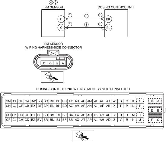
System Wiring Diagram
am6zzw00017917
|
Function Explanation (DTC Detection Outline)
Repeatability Verification Procedure
1. Perform the "COMPULSORY DIESEL PARTICULATE FILTER REGENERATION". (See COMPULSORY DIESEL PARTICULATE FILTER REGENERATION [SKYACTIV-D 2.2].)
2. Drive the vehicle at a constant speed of 80 km/h {50 mph}.
3. Drive the vehicle at a constant speed for 30 min while Maintaining the condition in Step 2.
PID Item/Simulation Item Used In Diagnosis
Function Inspection Using M-MDS
|
STEP |
INSPECTION |
RESULTS |
ACTION |
|---|---|---|---|
|
1
|
PURPOSE: IDENTIFY TRIGGER DTC FOR FREEZE FRAME DATA
• Is the DTC P2002:00 on FREEZE FRAME DATA?
|
Yes
|
Go to the next step.
|
|
No
|
Go to the troubleshooting procedure for DTC on FREEZE FRAME DATA.
|
||
|
2
|
VERIFY RELATED REPAIR INFORMATION AVAILABILITY
• Verify related Service Information availability.
• Is any related Service Information available?
|
Yes
|
Perform repair or diagnosis according to the available Service Information.
• If the vehicle is not repaired, go to the next step.
|
|
No
|
Go to the next step.
|
||
|
3
|
PURPOSE: RECORD FREEZE FRAME DATA/SNAPSHOT DATA AND DIAGNOSTIC MONITORING TEST RESULTS TO UTILIZE WITH REPEATABILITY VERIFICATION
• Record the FREEZE FRAME DATA/snapshot data and DIAGNOSTIC MONITORING TEST RESULTS (PM sensor) on the repair order.
|
—
|
Go to Troubleshooting Diagnostic Procedure to perform the procedure from step 1.
|
Troubleshooting Diagnostic Procedure
|
STEP |
INSPECTION |
RESULTS |
ACTION |
|---|---|---|---|
|
1
|
PURPOSE: INSPECT PM SENSOR CONNECTOR CONDITION
• Switch the ignition off.
• Disconnect the PM sensor connector.
• Inspect for poor connection (such as damaged/pulled-out pins, corrosion).
• Is there any malfunction?
|
Yes
|
Repair or replace the connector and/or terminals, then go to Step 6.
|
|
No
|
Go to the next step.
|
||
|
2
|
PURPOSE: INSPECT DOSING CONTROL UNIT CONNECTOR CONDITION
• Switch the ignition off.
• Disconnect the dosing control unit connector.
• Inspect for poor connection (such as damaged/pulled-out pins, corrosion).
• Is there any malfunction?
|
Yes
|
Repair or replace the connector and/or terminals, then go to Step 6.
|
|
No
|
Go to the next step.
|
||
|
3
|
INSPECT PM SENSOR SIGNAL CIRCUIT FOR SHORT TO POWER SUPPLY
• Verify that the PM sensor and dosing control unit connectors are disconnected.
• Switch the ignition ON (engine off).
• Measure the voltage at the following terminals (wiring harness-side):
• Is the voltage 0 V?
|
Yes
|
Go to the next step.
|
|
No
|
Refer to the wiring diagram and verify whether or not there is a common connector between the following terminals:
• PM sensor terminal B—dosing control unit terminal BK
• PM sensor terminal C—dosing control unit terminal BL
If there is a common connector:
• Determine the malfunctioning part by inspecting the common connector and the terminal for corrosion, damage, or pin disconnection, and the common wiring harness for a short to power supply.
• Repair or replace the malfunctioning part.
If there is no common connector:
• Repair or replace the wiring harness which has a short to power supply.
Go to Step 6.
|
||
|
4
|
PURPOSE: VISUALLY INSPECT PM SENSOR FOR SOOT ACCUMULATION
• Inspect the PM sensor.
• Is there any malfunction?
|
Yes
|
Replace the PM sensor, then go to Step 6.
|
|
No
|
Go to the next step.
|
||
|
5
|
PURPOSE: DETERMINE IF MALFUNCTION CAUSE IS PM SENSOR OR DIESEL PARTICULATE FILTER
• Remove the catalytic converter.
• Visually inspect the diesel particulate filter condition.
• Is the diesel particulate filter damaged?
|
Yes
|
Replace the catalytic converter, then go to the next step.
|
|
No
|
Replace the PM sensor, then go to the next step.
|
||
|
6
|
PURPOSE: VERIFICATION OF VEHICLE REPAIR COMPLETION
• Clear the DTC from the dosing control unit memory using the M-MDS.
• Implement the repeatability verification procedure.
• Perform the Pending Trouble Code Access Procedure.
• Is the same Pending DTC present?
|
Yes
|
Repeat the inspection from Step 1.
• If the malfunction recurs, replace the dosing control unit.
Go to the next step.
|
|
No
|
Go to the next step.
|
||
|
7
|
PURPOSE: VERIFY IF THERE IS ANY OTHER MALFUNCTION
• Is any other DTC or pending code stored?
|
Yes
|
Go to the applicable DTC inspection.
|
|
No
|
DTC troubleshooting completed.
|