DTC P214F:00 [DOSING CONTROL UNIT (SKYACTIV-D 2.2)]
id0102k1724900
DTC P214F:00 |
Urea tank heater control malfunction |
---|---|
DETECTION CONDITION
|
• With the following conditions met, the coil conductivity in the urea tank heater is the specified value or more.
MONITORING CONDITIONS
• Ignition switched ON (engine off or on)
• The operation time of the urea tank heater is 50 s or more, or the coil conductivity in the urea tank heater is lower than the value 50 times or more.
• Battery voltage: 11—16 V for a continuous 2 s
• Ignition switched ON (engine off): 5 min or more have elapsed
• The following DTCs are not detected:
Diagnostic support note
• This is a continuous monitor (CCM).
• The check engine light illuminates if the dosing control unit detects the above malfunction condition in two consecutive drive cycles or in one drive cycle while the DTC for same malfunction has been stored in the dosing control unit.
• PENDING CODE is available if the dosing control unit detects the above malfunction condition first driving cycle.
• FREEZE FRAME DATA/Snapshot data is available.
• DTC is stored in the dosing control unit memory.
|
FAIL-SAFE FUNCTION
|
• Restricts the maximum remaining distance to empty.
• Limits the upper limit of the engine speed.
|
POSSIBLE CAUSE
|
• Urea pump connectors or terminals malfunction
• Dosing control unit connector or terminals malfunction
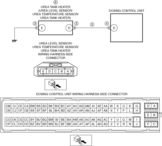
• Short to power supply in wiring harness between urea tank heater terminal D and dosing control unit terminal D
• Urea tank heater malfunction
• Dosing control unit malfunction
|
![]() |
Diagnostic Procedure
STEP |
INSPECTION |
RESULTS |
ACTION |
---|---|---|---|
1
|
RECORD VEHICLE STATUS AT TIME OF DTC DETECTION TO UTILIZE WITH REPEATABILITY VERIFICATION
• Record the snapshot data on the repair order.
|
—
|
Go to the next step.
|
2
|
VERIFY RELATED REPAIR INFORMATION AVAILABILITY
• Verify related Service Information availability.
• Is any related Service Information available?
|
Yes
|
Perform repair or diagnosis according to the available Service Information.
• If the vehicle is not repaired, go to the next step.
|
No
|
Go to the next step.
|
||
3
|
INSPECT UREA LEVEL SENSOR/UREA TEMPERATURE SENSOR/UREA TANK HEATER CONNECTOR CONDITION
• Switch the ignition off.
• Disconnect the urea level sensor/urea temperature sensor/urea tank heater connector.
• Inspect for poor connection (such as damaged/pulled-out pins, corrosion).
• Is there any malfunction?
|
Yes
|
Repair or replace the connector and/or terminals, then go to Step 7.
|
No
|
Go to the next step.
|
||
4
|
INSPECT DOSING CONTROL UNIT CONNECTOR CONDITION
• Disconnect the dosing control unit connector.
• Inspect for poor connection (such as damaged/pulled-out pins, corrosion).
• Is there any malfunction?
|
Yes
|
Repair or replace the connector and/or terminals, then go to Step 7.
|
No
|
Go to the next step.
|
||
5
|
INSPECT UREA TANK HEATER CONTROL CIRCUIT FOR SHORT TO POWER SUPPLY
• Verify that the urea level sensor/urea temperature sensor/urea tank heater and dosing control unit connectors are disconnected.
• Switch the ignition ON (engine off).
• Measure the voltage at the urea level sensor/urea temperature sensor/urea tank heater terminal D (wiring harness-side).
• Is the voltage 0 V?
|
Yes
|
Refer to the wiring diagram and verify whether or not there is a common connector between urea level sensor/urea temperature sensor/urea tank heater terminal D and dosing control unit terminal D.
If there is a common connector:
• Determine the malfunctioning part by inspecting the common connector and the terminal for corrosion, damage, or pin disconnection, and the common wiring harness for a short to power supply.
• Repair or replace the malfunctioning part.
If there is no common connector:
• Repair or replace the wiring harness which has a short to power supply.
Go to Step 7.
|
No
|
Go to the next step.
|
||
6
|
INSPECT UREA TANK HEATER
• Inspect the urea tank heater.
• Is there any malfunction?
|
Yes
|
Replace the Urea pump, then go to the next step.
|
No
|
Go to the next step.
|
||
7
|
VERIFY THAT ENGINE CAN BE STARTED
• Always reconnect all disconnected connectors.
• Clear the DTC from the dosing control unit memory using the M-MDS.
• Start the engine.
• Can the engine be started?
|
Yes
|
Go to the next step.
|
No
|
Perform the “SCR INDUCEMENT INSPECTION SERVICE FUNCTION” using the M-MDS.
Go to the next step.
|
||
8
|
IMPLEMENT THE REPEATABILITY VERIFICATION PROCEDURE
• Always reconnect all disconnected connectors.
• Leave the vehicle for 5 min.
• Leave for 10 min while idling.
• Has the restriction of the remaining distance to empty been canceled?
|
Yes
|
Go to the next step.
|
No
|
Repeat the inspection from Step 7.
|
||
9
|
VERIFY DTC TROUBLESHOOTING COMPLETED
• Retrieve the dosing control unit DTCs using the M-MDS.
• Is the same Pending DTC present?
|
Yes
|
Go to the next step.
|
No
|
Repeat the inspection from Step 1.
• If the malfunction recurs, replace the dosing control unit.
Go to the next step.
|
||
10
|
VERIFY IF OTHER DTCs DISPLAYED
• Are any other DTCs displayed?
|
Yes
|
Repair or replace the malfunctioning part according to the applicable DTC troubleshooting.
|
No
|
DTC troubleshooting completed.
|