 |
am6xuw00010710
EXHAUST SYSTEM REMOVAL/INSTALLATION [SKYACTIV-G 2.0, SKYACTIV-G 2.5 (WITHOUT CYLINDER DEACTIVATION)]
id0115q8800200
1. Disconnect the negative battery terminal. (See NEGATIVE BATTERY TERMINAL DISCONNECTION/CONNECTION.)
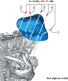
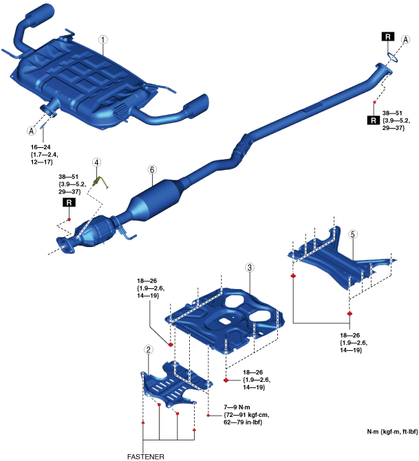
2. Remove in the order indicated in the table.
3. Remove the insulator. (See Exhaust System Insulator Removal/Installation.)
4. Install in the reverse order of removal.
Step 1
am6xuw00010710
|
|
1
|
Main silencer
|
|
2
|
Insulator
(See Insulator Installation Note.)
|
|
3
|
Brace bar
(See Brace Bar Removal Note.)
(See Brace Bar Installation Note.)
|
|
4
|
HO2S
|
|
5
|
Tunnel member
|
|
6
|
TWC
|
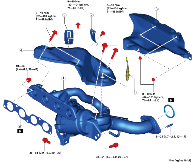
Step 2
am6xuw00010711
|
|
1
|
A/F sensor
|
|
2
|
Clip
|
|
3
|
Insulator
|
|
4
|
Exhaust manifold insulator
|
|
5
|
Exhaust manifold (WU-TWC)
|
|
6
|
Exhaust manifold gasket
|
Exhaust System Insulator Removal/Installation
1. Remove the exhaust system insulator in the order shown in the figure.
2. Install in the reverse order of removal.
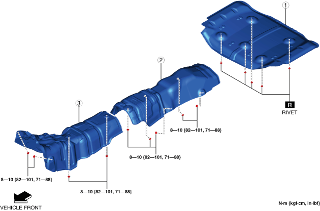
am6xuw00010712
|
|
1
|
Insulator (rear)
|
|
2
|
Insulator (middle)
|
|
3
|
Insulator (front)
|
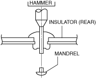
Insulator (rear) removal note
1. Push out the mandrel using a hammer and punch (2—2.8 mm {0.08—0.11 in} diameter).
ac5uuw00000434
|
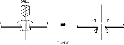
2. Remove the flange using a drill (5 mm {0.20 in} drill bit).
ar8uuw00001479
|
Brace Bar Removal Note
1. Remove the floor under cover. (See FLOOR UNDER COVER REMOVAL/INSTALLATION.)
2. Remove the brace bar.
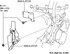
Exhaust Manifold Insulator Removal Note
1. Remove the insulator as shown in the figure.
ac5uuw00002678
|
2. Remove the No.1 engine mount rubber. (See ENGINE REMOVAL/INSTALLATION [SKYACTIV-G 2.0, SKYACTIV-G 2.5 (WITHOUT CYLINDER DEACTIVATION)].)
3. Move the engine.
4. Remove the exhaust manifold insulator.
Exhaust Manifold Removal Note
1. Remove the front crossmember. (See FRONT CROSSMEMBER REMOVAL/INSTALLATION.)
2. Remove the exhaust manifold.
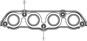
Exhaust Manifold Installation Note
1. Temporarily tighten the exhaust manifold installation nuts (1) and (2) shown in the figure by hand.
ac5uuw00002679
|
2. Tighten the exhaust manifold installation nuts (1) and (2) shown in the figure to 33—53 N·m {3.4—5.4 kgf·m, 25—39 ft·lbf}.
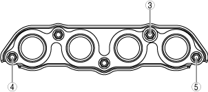
3. Temporarily tighten the exhaust manifold installation nuts (3) to (5) shown in the figure by hand.
ac5wzw00002715
|
4. Tighten the exhaust manifold installation nuts (3) to (5) shown in the figure.
5. Tighten the exhaust manifold installation nuts (1) and (2) shown in the figure.
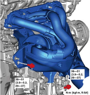
6. Temporarily tighten the bolts (6) and (7) shown in the figure.
ac5uuw00009265
|
7. Tighten the bolt (6) shown in the figure.
8. Tighten the bolt (7) shown in the figure.
Exhaust Manifold Insulator Installation Note
1. Temporarily tighten the exhaust manifold insulator.
2. Tighten the exhaust manifold insulator in the order shown in the figure.
ac5uuw00009266
|
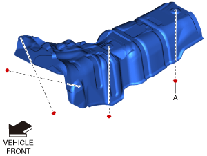
Insulator (front) installation note
1. Tighten nut A shown in the figure to the specified torque.
am6xuw00010713
|
2. Tighten the remaining nuts to the specified torque.
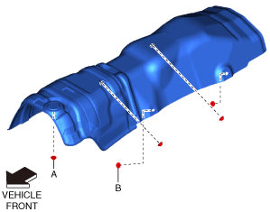
Insulator (middle) installation note
1. Tighten nut A shown in the figure to the specified torque.
am6xuw00010714
|
2. Tighten nut B shown in the figure to the specified torque.
3. Tighten the remaining nuts to the specified torque.
Insulator (rear) installation note
1. Install rivets A shown in the figure.
am6xuw00010715
|
2. Install the remaining rivets.
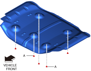
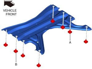
Tunnel Member Installation Note
1. Tighten bolt A shown in the figure to the specified torque.
am6xuw00012275
|
2. Tighten bolt B shown in the figure to the specified torque.
3. Tighten the remaining bolts to the specified torque.
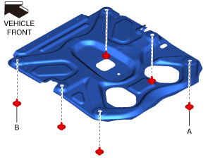
Brace Bar Installation Note
1. Tighten bolt A shown in the figure to the specified torque.
am6xuw00012276
|
2. Tighten bolt B shown in the figure to the specified torque.
3. Tighten the remaining bolts to the specified torque.
4. Install the floor under cover. (See FLOOR UNDER COVER REMOVAL/INSTALLATION.)
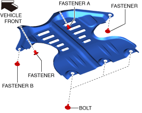
Insulator Installation Note
1. Install fastener A shown in the figure.
am6xuw00012277
|
2. Install fastener B shown in the figure.
3. Install the remaining fasteners.
4. Tighten the bolts shown in the figure to the specified torque.