 |
ac5uuw00007193
ENGINE REMOVAL/INSTALLATION [SKYACTIV-G 2.0, SKYACTIV-G 2.5 (WITHOUT CYLINDER DEACTIVATION)]
id0110s9800400
Engine Removal
1. Disconnect the negative battery terminal. (See NEGATIVE BATTERY TERMINAL DISCONNECTION/CONNECTION.)
2. Remove the front under cover No.1 and No.2. (See FRONT UNDER COVER No.1 REMOVAL/INSTALLATION.) (See FRONT UNDER COVER No.2 REMOVAL/INSTALLATION.)
3. Remove the front splash shield. (See SPLASH SHIELD REMOVAL/INSTALLATION.)
4. Drain the engine coolant. (See ENGINE COOLANT REPLACEMENT [SKYACTIV-G 2.0, SKYACTIV-G 2.5 (WITHOUT CYLINDER DEACTIVATION)].)
5. Drain the transaxle oil (MTX) or ATF (ATX). (See MANUAL TRANSAXLE OIL REPLACEMENT [C66M-R].) (See AUTOMATIC TRANSAXLE FLUID (ATF) REPLACEMENT [FW6A-EL].)
6. Remove the front wheels and tires. (See WHEEL AND TIRE REMOVAL/INSTALLATION.)
7. Remove the plug hole plate. (See PLUG HOLE PLATE REMOVAL/INSTALLATION [SKYACTIV-G 2.0, SKYACTIV-G 2.5 (WITHOUT CYLINDER DEACTIVATION)].)
8. Remove the air cleaner, air hose and fresh air duct as a single unit. (See INTAKE-AIR SYSTEM REMOVAL/INSTALLATION [SKYACTIV-G 2.0, SKYACTIV-G 2.5 (WITHOUT CYLINDER DEACTIVATION)].)
9. Remove the PCM component. (See PCM REMOVAL/INSTALLATION [SKYACTIV-G 2.0, SKYACTIV-G 2.5 (WITHOUT CYLINDER DEACTIVATION)].)
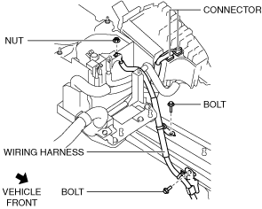
10. Remove the bolts, nut and connector shown in the figure, and set the wiring harness aside.
ac5uuw00007193
|
11. Remove the battery and battery tray. (See BATTERY REMOVAL/INSTALLATION [SKYACTIV-G 2.0, SKYACTIV-G 2.5 (WITHOUT CYLINDER DEACTIVATION)].)
12. Disconnect the selector cable. (ATX) (See AUTOMATIC TRANSAXLE SHIFT MECHANISM REMOVAL/INSTALLATION.)
13. Disconnect the control cable. (MTX) (See MANUAL TRANSAXLE SHIFT MECHANISM REMOVAL/INSTALLATION [C66M-R].)
14. Remove the clutch release cylinder with the pipe still connected. (MTX) (See CLUTCH RELEASE CYLINDER REMOVAL/INSTALLATION [C66M-R].)
15. Disconnect the vacuum hose. (See VACUUM HOSE REMOVAL/INSTALLATION [L.H.D. (SKYACTIV-G 2.0, SKYACTIV-G 2.5 (WITHOUT CYLINDER DEACTIVATION))].) (See VACUUM HOSE REMOVAL/INSTALLATION [R.H.D. (SKYACTIV-G 2.0, SKYACTIV-G 2.5 (WITHOUT CYLINDER DEACTIVATION))].)
16. Disconnect the evaporative hose. (See PURGE SOLENOID VALVE REMOVAL/INSTALLATION [SKYACTIV-G 2.0, SKYACTIV-G 2.5 (WITHOUT CYLINDER DEACTIVATION)].)
17. Disconnect the fuel hose. (See QUICK RELEASE CONNECTOR (FUEL SYSTEM) REMOVAL/INSTALLATION [SKYACTIV-G 2.0, SKYACTIV-G 2.5 (WITHOUT CYLINDER DEACTIVATION)].)
18. Disconnect the heater hoses. (See A/C UNIT REMOVAL/INSTALLATION.)
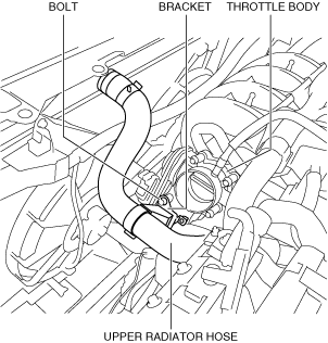
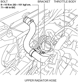
19. Remove the bracket shown in the figure from the throttle body.
ac5wzw00010773
|
20. Disconnect the upper radiator hose from the engine side.
21. Disconnect the lower radiator hose from the radiator.
22. Remove the generator drive belt. (See DRIVE BELT REMOVAL/INSTALLATION [SKYACTIV-G 2.0, SKYACTIV-G 2.5 (WITHOUT CYLINDER DEACTIVATION)].)
23. Remove the TWC installation nuts (exhaust manifold side) and secure the TWC using wire or rope so that it is out of the way. (See EXHAUST SYSTEM REMOVAL/INSTALLATION [SKYACTIV-G 2.0, SKYACTIV-G 2.5 (WITHOUT CYLINDER DEACTIVATION)].)
24. Disconnect the drive shaft from the transaxle side and set the drive shaft out of the way. (See FRONT DRIVE SHAFT REMOVAL/INSTALLATION.)
25. Remove the No.1 engine mount rubber and the front crossmember component as a single unit. (See FRONT CROSSMEMBER REMOVAL/INSTALLATION.)
26. Remove the A/C compressor with the cooler hose still connected and secure it using wire or rope so that it is out of the way. (See A/C COMPRESSOR REMOVAL/INSTALLATION [SKYACTIV-G 2.0, SKYACTIV-G 2.5].)
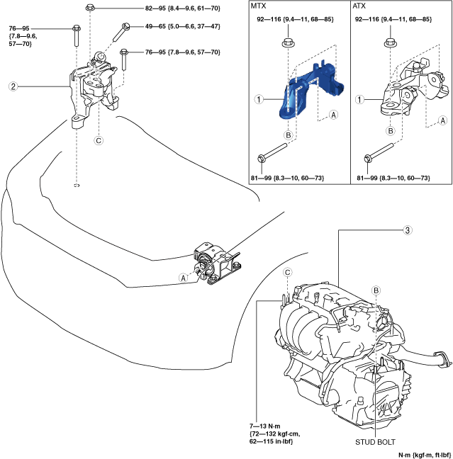
27. Remove in the order indicated in the table.
am6zzw00017985
|
|
1
|
No.4 engine mount bracket
|
|
2
|
No.3 engine mount
|
|
3
|
Engine, transaxle
|
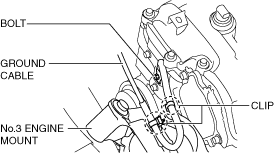
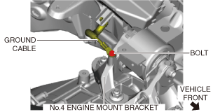
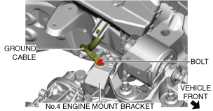
No.3 engine mount, No.4 engine mount bracket removal note
1. Remove the bolt and clips, and set the ground cable aside.
RH
ac5uuw00007007
|
LH (MTX)
am6xuw00010515
|
LH (ATX)
am6xuw00010516
|
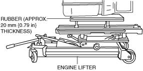
2. Secure the engine and transaxle using a commercially available engine lifter.
am6xuw00006689
|
3. Remove the No.4 engine mount bracket.
4. Remove the No.3 engine mount.
Engine Installation
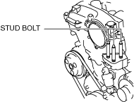
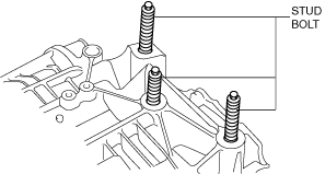
1. Tighten the engine front cover stud bolts.
am6xuw00006690
|
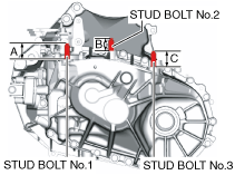
2. Measure the projection of the transaxle stud bolts. (MTX)
am6xuw00011730
|
3. Tighten the transaxle stud bolts. (ATX)
am6xuw00012315
|
4. Secure the engine and transaxle using a commercially available engine lifter.
am6xuw00006689
|
5. Return the engine and transaxle to their original positions.
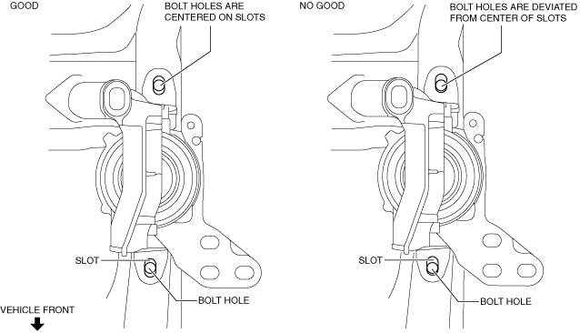
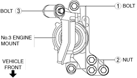
6. Temporarily tighten the No.3 engine mount installation bolts and nuts using the following procedure:
ac5uuw00007013
|
ac5uuw00007014
|
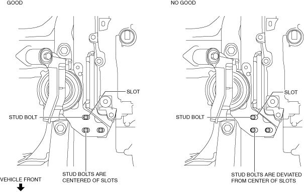
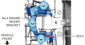
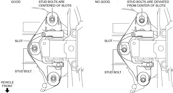
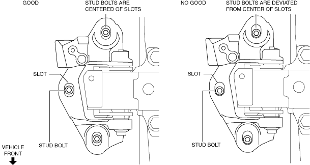
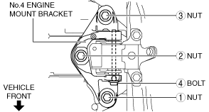
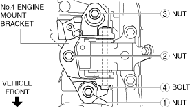
7. Temporarily tighten the No.4 engine mount bracket installation bolt and nuts using the following procedure:
MTX
ac5uuw00007015
|
ATX
am6xuw00010517
|
MTX
ac5uuw00007017
|
ATX
ac5uuw00007018
|
8. Install the No.1 engine mount rubber and the front crossmember component as a single unit. (See FRONT CROSSMEMBER REMOVAL/INSTALLATION.)
9. Tighten the No.3 engine mount installation bolts and nuts in the order shown in the figure.
am6zzw00017986
|
Tightening torque
|
Installation position |
Tightening torque |
|---|---|
|
1
|
76—95 N·m {7.8—9.6 kgf·m, 57—70 ft·lbf}
|
|
2
|
82—95 N·m {8.4—9.6 kgf·m, 61—70 ft·lbf}
|
|
3
|
49—65 N·m {5.0—6.6 kgf·m, 37—47 ft·lbf}
|
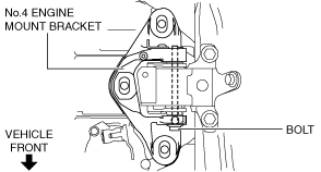
10. Tighten the No.4 engine mount bracket installation bolt and nuts in the order shown in the figure.
MTX
am6xuw00010518
|
ATX
ac5uuw00007021
|
Tightening torque
|
Installation position |
Tightening torque |
|---|---|
|
1, 2, 3
|
92—116 N·m {9.4—11 kgf·m, 68—85 ft·lbf}
|
|
4
|
81—99 N·m {8.3—10 kgf·m, 60—73 ft·lbf}
|
11. Tighten the No.1 engine mount rubber installation bolts.
ac5uuw00007022
|
Tightening torque
|
Installation position |
Tightening torque |
|---|---|
|
1
|
141—172 N·m {15—17 kgf·m, 104—126 ft·lbf}
|
|
2
|
130—164 N·m {14—16 kgf·m, 96—120 ft·lbf}
|
12. Connect the ground cable shown in the figure.
RH
ac5uuw00007007
|
LH (MTX)
am6xuw00010515
|
LH (ATX)
am6xuw00010516
|
13. Install the A/C compressor. (See A/C COMPRESSOR REMOVAL/INSTALLATION [SKYACTIV-G 2.0, SKYACTIV-G 2.5].)
14. Install the front drive shaft. (See FRONT DRIVE SHAFT REMOVAL/INSTALLATION.)
15. Install the TWC. (See EXHAUST SYSTEM REMOVAL/INSTALLATION [SKYACTIV-G 2.0, SKYACTIV-G 2.5 (WITHOUT CYLINDER DEACTIVATION)].)
16. Install the generator drive belt. (See DRIVE BELT REMOVAL/INSTALLATION [SKYACTIV-G 2.0, SKYACTIV-G 2.5 (WITHOUT CYLINDER DEACTIVATION)].)
17. Connect the lower radiator hose to the radiator.
18. Install the front wheels and tires. (See WHEEL AND TIRE REMOVAL/INSTALLATION.)
19. Install the bracket shown in the figure to the throttle body.
ac5wzw00010776
|
20. Connect the upper radiator hose to the engine side.
21. Connect the heater hoses. (See A/C UNIT REMOVAL/INSTALLATION.)
22. Connect the fuel hose. (See QUICK RELEASE CONNECTOR (FUEL SYSTEM) REMOVAL/INSTALLATION [SKYACTIV-G 2.0, SKYACTIV-G 2.5 (WITHOUT CYLINDER DEACTIVATION)].)
23. Connect the evaporative hose. (See PURGE SOLENOID VALVE REMOVAL/INSTALLATION [SKYACTIV-G 2.0, SKYACTIV-G 2.5 (WITHOUT CYLINDER DEACTIVATION)].)
24. Connect the vacuum hose. (See VACUUM HOSE REMOVAL/INSTALLATION [L.H.D. (SKYACTIV-G 2.0, SKYACTIV-G 2.5 (WITHOUT CYLINDER DEACTIVATION))].)(See VACUUM HOSE REMOVAL/INSTALLATION [R.H.D. (SKYACTIV-G 2.0, SKYACTIV-G 2.5 (WITHOUT CYLINDER DEACTIVATION))].)
25. Install the clutch release cylinder. (MTX) (See CLUTCH RELEASE CYLINDER REMOVAL/INSTALLATION [C66M-R].)
26. Connect the control cable. (MTX) (See MANUAL TRANSAXLE SHIFT MECHANISM REMOVAL/INSTALLATION [C66M-R].)
27. Connect the selector cable. (ATX) (See AUTOMATIC TRANSAXLE SHIFT MECHANISM REMOVAL/INSTALLATION.)
28. Install the battery tray and battery. (See BATTERY REMOVAL/INSTALLATION [SKYACTIV-G 2.0, SKYACTIV-G 2.5 (WITHOUT CYLINDER DEACTIVATION)].)
29. Connect the wiring harness shown in the figure.
am6xuw00012316
|
30. Install the PCM component. (See PCM REMOVAL/INSTALLATION [SKYACTIV-G 2.0, SKYACTIV-G 2.5 (WITHOUT CYLINDER DEACTIVATION)].)
31. Install the air cleaner, air hose and fresh air duct as a single unit. (See INTAKE-AIR SYSTEM REMOVAL/INSTALLATION [SKYACTIV-G 2.0, SKYACTIV-G 2.5 (WITHOUT CYLINDER DEACTIVATION)].)
32. Connect the negative battery terminal. (See NEGATIVE BATTERY TERMINAL DISCONNECTION/CONNECTION.)
33. Refill the transaxle oil (MTX) or ATF (ATX). (See MANUAL TRANSAXLE OIL REPLACEMENT [C66M-R].) (See AUTOMATIC TRANSAXLE FLUID (ATF) REPLACEMENT [FW6A-EL].)
34. Refill the engine coolant. (See ENGINE COOLANT REPLACEMENT [SKYACTIV-G 2.0, SKYACTIV-G 2.5 (WITHOUT CYLINDER DEACTIVATION)].)
35. Start the engine, and inspect and adjust the following:
36. Install the front splash shield. (See SPLASH SHIELD REMOVAL/INSTALLATION.)
37. Install the front under cover No.1 and No.2. (See FRONT UNDER COVER No.1 REMOVAL/INSTALLATION.) (See FRONT UNDER COVER No.2 REMOVAL/INSTALLATION.)
38. Install the plug hole plate. (See PLUG HOLE PLATE REMOVAL/INSTALLATION [SKYACTIV-G 2.0, SKYACTIV-G 2.5 (WITHOUT CYLINDER DEACTIVATION)].)