 |
am6xuw00011355
FRONT STABILIZER INSTALLATION
id021300803500
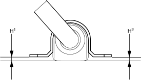
1. After installing the front stabilizer bracket, verify that the positions of the front stabilizer bracket and the front stabilizer bushing are within the range shown in the figure.
am6xuw00011355
|
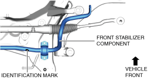
2. Assemble the front stabilizer component so that the identification mark is on the right side of the vehicle.
am6xuw00011357
|
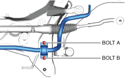
3. Temporarily tighten bolts A and B shown in the figure.
am6xuw00011358
|
4. Tighten bolt B.
5. Tighten bolt A.
6. Tighten bolt B.
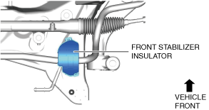
7. Install the front stabilizer insulator.
am6xuw00011359
|
8. Install the front crossmember component. (See FRONT CROSSMEMBER REMOVAL/INSTALLATION.)
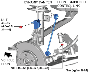
9. Install the dynamic damper and front stabilizer control link.
am6xuw00011360
|
10. Connect the intermediate shaft to the steering gear and linkage. (See STEERING WHEEL AND COLUMN REMOVAL/INSTALLATION.)
11. Install the joint cover. (See STEERING WHEEL AND COLUMN REMOVAL/INSTALLATION.)
12. Assemble the front lower arm ball joint to the steering knuckle. (See FRONT LOWER ARM REMOVAL/INSTALLATION.)
13. Assemble the tie-rod end to the steering knuckle. (See TIE-ROD END REPLACEMENT.)
14. Install the front splash shield. (See SPLASH SHIELD REMOVAL/INSTALLATION.)
15. Install the front under cover No.1. (See FRONT UNDER COVER No.1 REMOVAL/INSTALLATION.)
16. Install the front under cover No.2. (See FRONT UNDER COVER No.2 REMOVAL/INSTALLATION.)
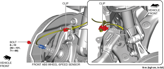
17. Assemble the front ABS wheel-speed sensor and the wiring harness clip as shown in the figure.
am6xuw00011361
|
18. Install the wheels and tires. (See WHEEL AND TIRE REMOVAL/INSTALLATION.)
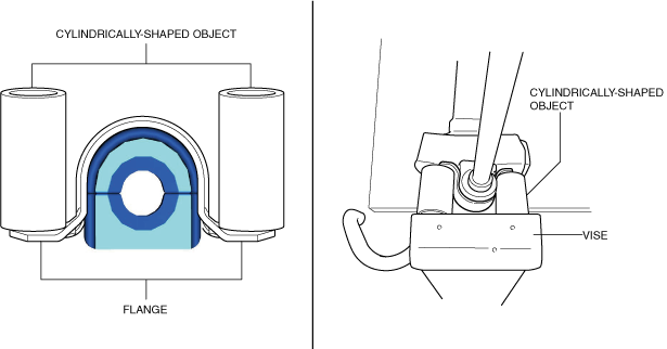
Front Stabilizer Bracket Installation Note
1. If the front stabilizer bracket cannot be installed by hand, install it using a vise.
am6xuw00011362
|