 |
ac5uuw00008270
VACUUM PUMP REMOVAL/INSTALLATION [SKYACTIV-D 2.2]
id0411008036s8
1. Disconnect the negative battery terminal. (See NEGATIVE BATTERY TERMINAL DISCONNECTION/CONNECTION.)
2. Remove the engine cover. (See ENGINE COVER REMOVAL/INSTALLATION [SKYACTIV-D 2.2].)
3. Remove the battery and battery tray. (See BATTERY REMOVAL/INSTALLATION [SKYACTIV-D 2.2].)
4. Remove the following parts as a single unit. (See INTAKE-AIR SYSTEM REMOVAL/INSTALLATION [SKYACTIV-D 2.2].)
5. Disconnect the blow-by heater connector.(See INTAKE-AIR SYSTEM REMOVAL/INSTALLATION [SKYACTIV-D 2.2].)
6. Set the turbocharger air inlet hose aside. (See INTAKE-AIR SYSTEM REMOVAL/INSTALLATION [SKYACTIV-D 2.2].)
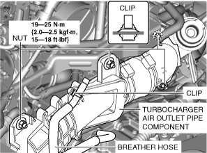
7. Remove the turbocharger air inlet pipe and the breather hose as a single unit. (See INTAKE-AIR SYSTEM REMOVAL/INSTALLATION [SKYACTIV-D 2.2].)
8. Pinch open the clamp using pliers and disconnect the vacuum hose from the vacuum pump. (See VACUUM HOSE REMOVAL/INSTALLATION [L.H.D. (SKYACTIV-D 2.2)].) (See VACUUM HOSE REMOVAL/INSTALLATION [R.H.D. (SKYACTIV-D 2.2)].)
9. Disconnect the clip.
ac5uuw00008270
|
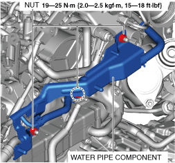
10. Remove the nuts and set the turbocharger air outlet pipe component aside.
11. Remove the nuts and set the water pipe component aside.
ac5uuw00008271
|
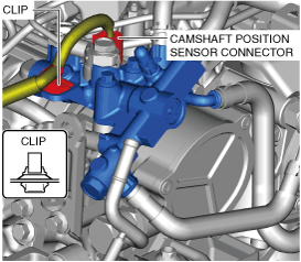
12. Disconnect the connectors and clip shown in the figure.
ac5uuw00008272
|
13. Perform the “BEFORE SERVICE PRECAUTION”. (See BEFORE SERVICE PRECAUTION [SKYACTIV-D 2.2].)
14. Remove the following parts. (See SUPPLY PUMP REMOVAL/INSTALLATION [SKYACTIV-D 2.2].)
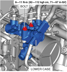
15. Remove the bolts and set the lower case aside.
ac5uuw00008273
|
16. Remove the insulator installation bolts. (See EGR PIPE REMOVAL/INSTALLATION [SKYACTIV-D 2.2].)
17. To facilitate the removal of the vacuum pump, tilt the insulator so that the vacuum pump installation bolt is visible.
18. Remove in the order indicated in the table.
19. Install in the reverse order of removal.
20. Perform the “AFTER SERVICE PRECAUTION”. (See AFTER SERVICE PRECAUTION [SKYACTIV-D 2.2].)
am6zzw00008770
|
|
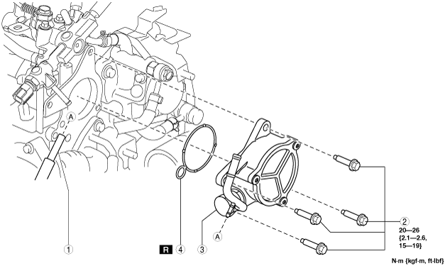
1
|
Vacuum tube
|
|
2
|
Bolt
|
|
3
|
Vacuum pump
(See Vacuum Pump Removal Note.)
|
|
4
|
O-ring
|
Vacuum Pump Removal Note
1. When removing the vacuum pump, place a rag under the installation surface of the vacuum pump so that engine oil does not get on other parts.
2. Remove the vacuum pump.
Vacuum Pump and O-ring Installation Note
1. Rotate the vacuum pump by hand to drain the remainder of the engine oil in the vacuum pump.
2. Degrease the O-ring installation groove and installation surface.
3. Install the new O-ring to the vacuum pump.
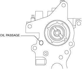
4. Insert a cloth into the oil passage shown in the figure.
am6zzw00014679
|
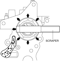
5. Scrape the cylinder head from the inside to the outside using a scraper and clean away the remaining silicone sealant on the cylinder head so that it does not get in the cylinder head.
am6zzw00014680
|
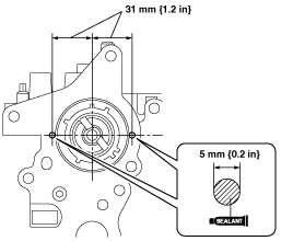
6. Clean the cylinder head.
7. Apply silicone sealant (TB1217D or equivalent) to the positions shown in the figure.
am6zzw00008493
|
8. Install the vacuum pump.