 |
ac5uuw00006401
SHIFT CONTROL MODULE REMOVAL/INSTALLATION [C66M-R]
id0515m8160200
1. Shift the shift lever to the neutral position.
2. Disconnect the negative battery terminal. (See NEGATIVE BATTERY TERMINAL DISCONNECTION/CONNECTION.)
3. Remove the plug hole plate. (See PLUG HOLE PLATE REMOVAL/INSTALLATION [SKYACTIV-G 2.0, SKYACTIV-G 2.5 (WITHOUT CYLINDER DEACTIVATION)].)
4. Remove the following parts as a single unit. (See INTAKE-AIR SYSTEM REMOVAL/INSTALLATION [SKYACTIV-G 2.0, SKYACTIV-G 2.5 (WITHOUT CYLINDER DEACTIVATION)].)
5. Remove the battery. (See BATTERY REMOVAL/INSTALLATION [SKYACTIV-G 2.0, SKYACTIV-G 2.5 (WITHOUT CYLINDER DEACTIVATION)].)
6. Remove the PCM component. (See PCM REMOVAL/INSTALLATION [SKYACTIV-G 2.0, SKYACTIV-G 2.5 (WITHOUT CYLINDER DEACTIVATION)].)
7. Remove the battery tray. (See BATTERY REMOVAL/INSTALLATION [SKYACTIV-G 2.0, SKYACTIV-G 2.5 (WITHOUT CYLINDER DEACTIVATION)].)
8. Disconnect the control cable from the manual transaxle. (See MANUAL TRANSAXLE SHIFT MECHANISM REMOVAL/INSTALLATION [C66M-R].)
9. Remove the neutral switch. (See NEUTRAL SWITCH REMOVAL/INSTALLATION [C66M-R].)
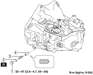
10. Remove the detent ball pin in the order shown in the figure.
ac5uuw00006401
|
|
1
|
Plug
|
|
2
|
Gasket
|
|
3
|
Spring
|
|
4
|
Detent ball pin
|
11. Remove the back-up light switch. (See BACK-UP LIGHT SWITCH REMOVAL/INSTALLATION [C66M-R].)
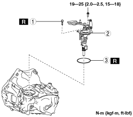
12. Remove the shift control module in the order shown in the figure.
ac5uuw00006402
|
|
1
|
Breather
|
|
2
|
Shift control module
|
|
3
|
O-ring
|
13. Install in the reverse order of removal.
Shift Control Module Installation Note
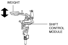
1. Verify that the shift control module is in the neutral position.
ac5uuw00002962
|
2. Install the shift control module.
Control Cable Ends (Transaxle Side) Installation Note
1. Verify that the shift control module is in the neutral position.
2. Connect the control cable to the manual transaxle. (See MANUAL TRANSAXLE SHIFT MECHANISM REMOVAL/INSTALLATION [C66M-R].)
3. Make sure that the shift lever can be shifted smoothly.