|
1
|
VERIFY REAR BODY CONTROL MODULE (RBCM) DTCs AGAIN
• Clear the DTC for the rear body control module (RBCM) using the M-MDS.
• Depress the brake pedal.
• Retrieve the rear body control module (RBCM) DTCs using the M-MDS.
• Is the same Pending DTC present?
|
Yes
|
Go to the next step.
|
|
No
|
Go to Step 17.
|
|
2
|
INSPECT REAR COMBINATION LIGHT (LH) CONNECTOR CONDITION
• Switch the ignition off.
• Disconnect the negative battery terminal.
• Disconnect the rear combination light (LH) connector.
• Inspect the connector engagement and connection condition and inspect the terminals for damage, deformation, corrosion, or disconnection.
• Is the connector normal?
|
Yes
|
Go to the next step.
|
|
No
|
Repair or replace the connector, then go to Step 16.
|
|
3
|
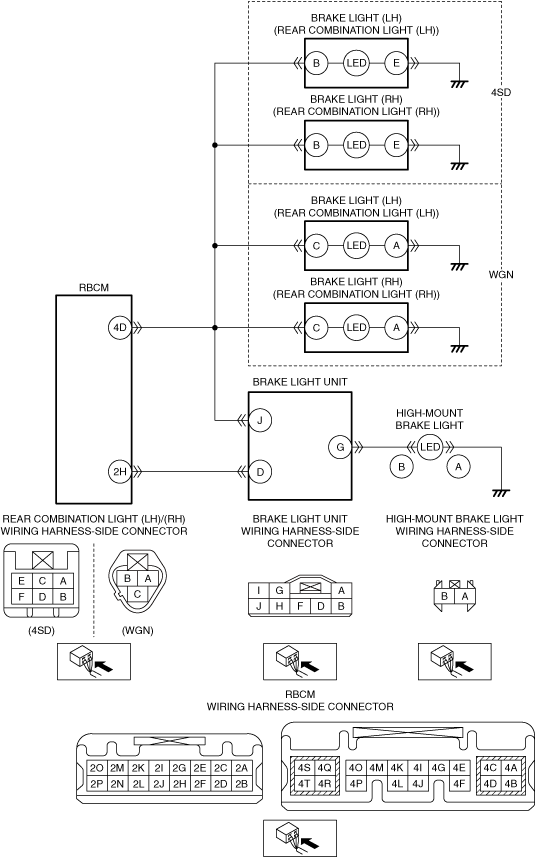
INSPECT FOR OPEN CIRCUIT IN BRAKE LIGHT (LH) (COMBINATION LIGHT (LH)) GROUND CIRCUIT
• Verify that the rear combination light (LH) connector is disconnected.
• Inspect for continuity between the following harnesses:
-
― Rear combination light (LH) terminal E—Body ground (4SD)
― Rear combination light (LH) terminal A—Body ground (WGN)
• Is there continuity?
|
Yes
|
Go to the next step.
|
|
No
|
Refer to the wiring diagram and verify whether or not there is a common connector between the following terminals:
• Rear combination light (LH) terminal E—Body ground (4SD)
• Rear combination light (LH) terminal A—Body ground (WGN)
If there is a common connector:
• Determine the malfunctioning part by inspecting the common connector and the terminal for corrosion, damage, or pin disconnection, and the common wiring harness for an open circuit.
• Repair or replace the malfunctioning part.
If there is no common connector:
• Repair or replace the wiring harness which has an open circuit.
Go to Step 16.
|
|
4
|
INSPECT REAR COMBINATION LIGHT (RH) CONNECTOR CONDITION
• Disconnect the rear combination light (RH) connector.
• Inspect the connector engagement and connection condition and inspect the terminals for damage, deformation, corrosion, or disconnection.
• Is the connector normal?
|
Yes
|
Go to the next step.
|
|
No
|
Repair or replace the connector, then go to Step 16.
|
|
5
|
INSPECT FOR OPEN CIRCUIT IN BRAKE LIGHT (RH) (COMBINATION LIGHT (RH)) GROUND CIRCUIT
• Verify that the rear combination light (RH) connector is disconnected.
• Inspect for continuity between the following harnesses:
-
― Rear combination light (RH) terminal E—Body ground (4SD)
― Rear combination light (RH) terminal A—Body ground (WGN)
• Is there continuity?
|
Yes
|
Go to the next step.
|
|
No
|
Refer to the wiring diagram and verify whether or not there is a common connector between the following terminals:
• Rear combination light (RH) terminal E—Body ground (4SD)
• Rear combination light (RH) terminal A—Body ground (WGN)
If there is a common connector:
• Determine the malfunctioning part by inspecting the common connector and the terminal for corrosion, damage, or pin disconnection, and the common wiring harness for an open circuit.
• Repair or replace the malfunctioning part.
If there is no common connector:
• Repair or replace the wiring harness which has an open circuit.
Go to Step 16.
|
|
6
|
INSPECT HIGH-MOUNT BRAKE LIGHT CONNECTOR CONDITION
• Disconnect the high-mount brake light connector.
• Inspect the connector engagement and connection condition and inspect the terminals for damage, deformation, corrosion, or disconnection.
• Is the connector normal?
|
Yes
|
Go to the next step.
|
|
No
|
Repair or replace the connector, then go to Step 16.
|
|
7
|
INSPECT FOR OPEN CIRCUIT IN HIGH-MOUNT BRAKE LIGHT GROUND CIRCUIT
• Verify that the high-mount brake light connector is disconnected.
• Inspect for continuity between high-mount brake light terminal A (wiring harness-side) and body ground.
• Is there continuity?
|
Yes
|
Go to the next step.
|
|
No
|
Refer to the wiring diagram and verify whether or not there is a common connector between high-mount brake light terminal A and body ground.
If there is a common connector:
• Determine the malfunctioning part by inspecting the common connector and the terminal for corrosion, damage, or pin disconnection, and the common wiring harness for an open circuit.
• Repair or replace the malfunctioning part.
If there is no common connector:
• Repair or replace the wiring harness which has an open circuit.
Go to Step 16.
|
|
8
|
INSPECT BRAKE LIGHT UNIT CONNECTOR CONDITION
• Disconnect the brake light unit connector.
• Inspect the connector engagement and connection condition and inspect the terminals for damage, deformation, corrosion, or disconnection.
• Is the connector normal?
|
Yes
|
Go to the next step.
|
|
No
|
Repair or replace the connector, then go to Step 16.
|
|
9
|
INSPECT REAR BODY CONTROL MODULE (RBCM) CONNECTOR CONDITION
• Disconnect the rear body control module (RBCM) connector.
• Inspect the connector engagement and connection condition and inspect the terminals for damage, deformation, corrosion, or disconnection.
• Is the connector normal?
|
Yes
|
Go to the next step.
|
|
No
|
Repair or replace the connector, then go to Step 16.
|
|
10
|
INSPECT BRAKE LIGHT CIRCUIT FOR SHORT TO GROUND
• Verify that the rear combination light (LH), rear combination light (RH), high-mount brake light, brake light unit and rear body control module (RBCM) connectors are disconnected.
• Inspect for continuity between the following terminals (wiring harness-side) and body ground:
-
― Rear body control module (RBCM) terminal 4D
― High-mount brake light terminal B
• Is there continuity?
|
Yes
|
Refer to the wiring diagram and verify whether or not there is a common connector between the following terminals:
• Rear body control module (RBCM) terminal 4D—Rear combination light (LH) terminal B (4SD)
• Rear body control module (RBCM) terminal 4D—Rear combination light (RH) terminal B (4SD)
• Rear body control module (RBCM) terminal 4D—Rear combination light (LH) terminal C (WGN)
• Rear body control module (RBCM) terminal 4D—Rear combination light (RH) terminal C (WGN)
• Rear body control module (RBCM) terminal 4D—Brake light unit terminal J
• High-mount brake light terminal B—Brake light unit terminal G
If there is a common connector:
• Determine the malfunctioning part by inspecting the common connector and the terminal for corrosion, damage, or pin disconnection, and the common wiring harness for a short to ground.
• Repair or replace the malfunctioning part.
If there is no common connector:
• Repair or replace the wiring harness which has a short to ground.
Go to Step 16.
|
|
No
|
Go to the next step.
|
|
11
|
INSPECT FOR SHORT TO POWER SUPPLY IN BRAKE LIGHT CIRCUIT
• Verify that the rear combination light (LH), rear combination light (RH), high-mount brake light, brake light unit and rear body control module (RBCM) connectors are disconnected.
• Reconnect the negative battery terminal.
• Switch the ignition ON (engine off or on).
• Measure the voltage at the following terminals (wiring harness-side):
-
― Rear body control module (RBCM) terminal 4D
― High-mount brake light terminal B
• Is the voltage 0 V?
|
Yes
|
Go to the next step.
|
|
No
|
Refer to the wiring diagram and verify whether or not there is a common connector between the following terminals:
• Rear body control module (RBCM) terminal 4D—Rear combination light (LH) terminal B (4SD)
• Rear body control module (RBCM) terminal 4D—Rear combination light (RH) terminal B (4SD)
• Rear body control module (RBCM) terminal 4D—Rear combination light (LH) terminal C (WGN)
• Rear body control module (RBCM) terminal 4D—Rear combination light (RH) terminal C (WGN)
• Rear body control module (RBCM) terminal 4D—Brake light unit terminal J
• High-mount brake light terminal B—Brake light unit terminal G
If there is a common connector:
• Determine the malfunctioning part by inspecting the common connector and the terminal for corrosion, damage, or pin disconnection, and the common wiring harness for a short to power supply.
• Repair or replace the malfunctioning part.
If there is no common connector:
• Repair or replace the wiring harness which has a short to power supply.
Go to Step 16.
|
|
12
|
INSPECT FOR OPEN CIRCUIT BRAKE LIGHT CIRCUIT
• Switch the ignition off.
• Disconnect the negative battery terminal.
• Verify that the rear combination light (LH), rear combination light (RH), high-mount brake light, brake light unit and rear body control module (RBCM) connectors are disconnected.
• Inspect for continuity between the following terminals (wiring harness-side):
-
― Rear body control module (RBCM) terminal 4D—Rear combination light (LH) terminal B (4SD)
― Rear body control module (RBCM) terminal 4D—Rear combination light (RH) terminal B (4SD)
― Rear body control module (RBCM) terminal 4D—Rear combination light (LH) terminal C (WGN)
― Rear body control module (RBCM) terminal 4D—Rear combination light (RH) terminal C (WGN)
― Rear body control module (RBCM) terminal 4D—Brake light unit terminal J
― Rear body control module (RBCM) terminal 2H—Brake light unit terminal D
― High-mount brake light terminal B—Brake light unit terminal G
• Is there continuity?
|
Yes
|
Go to the next step.
|
|
No
|
Refer to the wiring diagram and verify whether or not there is a common connector between the following terminals:
• Rear body control module (RBCM) terminal 4D—Rear combination light (LH) terminal B (4SD)
• Rear body control module (RBCM) terminal 4D—Rear combination light (RH) terminal B (4SD)
• Rear body control module (RBCM) terminal 4D—Rear combination light (LH) terminal C (WGN)
• Rear body control module (RBCM) terminal 4D—Rear combination light (RH) terminal C (WGN)
• Rear body control module (RBCM) terminal 4D—Brake light unit terminal J
• Rear body control module (RBCM) terminal 2H—Brake light unit terminal D
• High-mount brake light terminal B—Brake light unit terminal G
If there is a common connector:
• Determine the malfunctioning part by inspecting the common connector and the terminal for corrosion, damage, or pin disconnection, and the common wiring harness for an open circuit.
• Repair or replace the malfunctioning part.
If there is no common connector:
• Repair or replace the wiring harness which has an open circuit.
Go to Step 16.
|
|
13
|
INSPECT BRAKE LIGHT
• Reconnect the rear combination light (LH), rear combination light (RH), and rear body control module (RBCM) connectors.
• Verify that the brake light unit connector is disconnected.
• Reconnect the negative battery terminal.
• Switch the ignition ON (engine off or on).
• Turn on/off the brake light using simulation item STOP_LMP_CS.
• Are there any lights among the following which are not turned on/off according to the simulation operation?
-
― Brake light (LH) (rear combination light (LH))
― Brake light (RH) (rear combination light (RH))
|
Yes
|
If the brake light (LH) (rear combination light (LH)) does not turn on/off:
• Replace the rear combination light (LH).
If the brake light (RH) (rear combination light (RH)) does not turn on/off:
• Replace the rear combination light (RH).
Go to Step 16.
|
|
No
|
Go to the next step.
|
|
14
|
PERFORM DTC INSPECTION AND VERIFY HIGH-MOUNT BRAKE LIGHT MALFUNCTION
• Always reconnect all disconnected connectors.
• Reconnect the negative battery terminal.
• Clear the DTC for the rear body control module (RBCM) using the M-MDS.
• Depress the brake pedal.
• Retrieve the rear body control module (RBCM) DTCs using the M-MDS.
• Is the same Pending DTC present?
|
Yes
|
Replace the high-mount brake light, then go to the next step.
|
|
No
|
Go to Step 17.
|
|
15
|
INSPECT BRAKE LIGHT UNIT
• Inspect the brake light unit.
• Is the brake light unit normal?
|
Yes
|
Go to the next step.
|
|
No
|
Replace the brake light unit, then go to the next step.
|
|
16
|
VERIFY THAT REPAIRS HAVE BEEN COMPLETED
• Always reconnect all disconnected connectors.
• Reconnect the negative battery terminal.
• Clear the DTC for the rear body control module (RBCM) using the M-MDS.
• Depress the brake pedal.
• Retrieve the rear body control module (RBCM) DTCs using the M-MDS.
• Is the same Pending DTC present?
|
Yes
|
Repeat the inspection from Step 1.
• If the malfunction recurs, replace the rear body control module (RBCM).
Go to the next step.
|
|
No
|
Go to the next step.
|
|
17
|
VERIFY IF OTHER DTCs DISPLAYED
• Are any other DTCs displayed?
|
Yes
|
Repair or replace the malfunctioning part according to the applicable DTC troubleshooting.
|
|
No
|
DTC troubleshooting completed.
|