THROTTLE POSITION (TP) SENSOR INSPECTION [LF, L3]
id0140008027a6
-
Note
-
• Perform the following inspection only when directed.
Resistance Inspection
1. Perform the following test only when directed.
-
• If as specified but TP PID value is out of specification, inspect resistance of TP sensor.
-
• If not as specified, inspect the following:
-
- Accelerator cable free play (See ACCELERATOR CABLE INSPECTION/ADJUSTMENT [LF, L3].)
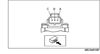
2. Disconnect the TP sensor connector.
3. Verify that the resistance between TP sensor terminals A and B changes smoothly while opening and closing the throttle valve slowly.
-
• If not verified, replace TP sensor.
4. Measure the resistance between TP sensor terminals A and C using an ohmmeter.
-
• If not as specified, replace the TP sensor.
-
• If as specified, but TP PID value is out of specification, perform the "Circuit Open/Short Inspection".
-
Specification
-
3.2-4.8 kilohms
Circuit Open/Short Inspection
1. Disconnect the PCM connector. (See PCM REMOVAL/INSTALLATION [LF, L3].)
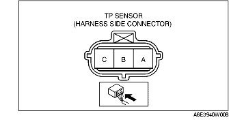
2. Inspect the following wiring harnesses for open or short. (Continuity check)
Open circuit
-
• If there is no continuity, the circuit is open. Repair or replace the harness.
-
- TP sensor terminal A (harness-side) and PCM terminal 2H (harness-side)
-
- TP sensor terminal B (harness-side) and PCM terminal 2A (harness-side)
-
- TP sensor terminal C (harness-side) and PCM terminal 2K (harness-side)
Short circuit
-
• If there is continuity, the circuit is shorted. Repair or replace the harness.
-
- TP sensor terminal C (harness-side) and power supply
-
- TP sensor terminal C (harness-side) and body GND
-
- TP sensor terminal B (harness-side) and power supply
-
- TP sensor terminal B (harness-side) and body GND
-
- TP sensor terminal A (harness-side) and power supply