1. Remove the battery, battery tray and battery bracket.
2. Remove the air cleaner component. (See INTAKE-AIR SYSTEM REMOVAL/INSTALLATION [LF, L3].)
3. Remove the wheels, tires and splash shields.
4. Remove the under cover.
5. Remove the steering gear and power steering pipe. (See STEERING GEAR AND LINKAGE REMOVAL/INSTALLATION.)
6. Remove the front auto leveling sensor. (See FRONT AUTO LEVELING SENSOR REMOVAL/INSTALLATION.)
7. Drain the transaxle oil into a suitable container.
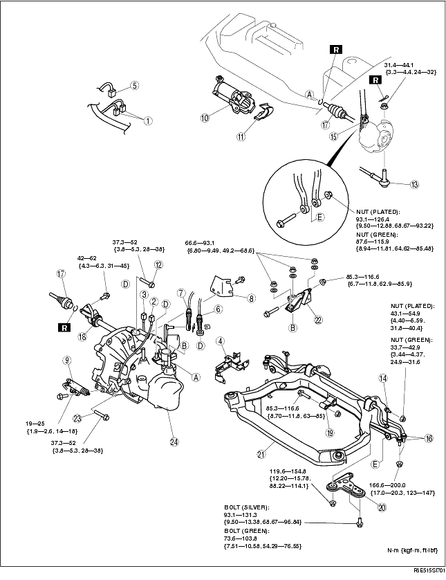
8. Remove in the order indicated in the table.
9. Install in the reverse order of removal.
10. Adjust the headlight zeroset. (See HEADLIGHT ZEROSET.)
11. Add the specified amount of specified transaxle oil.
12. Install the air cleaner component. (See INTAKE-AIR SYSTEM REMOVAL/INSTALLATION [LF, L3].)
13. Warm up the engine and transaxle, inspect for oil leakage, and inspect the transaxle operation.
.
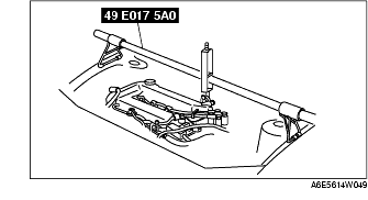
1. Support the engine using the SST before removing the No.1 engine mount.
2. Remove the No.1 engine mount.
1. Loosen the SST (49 E017 5A0) and lean the engine toward the transaxle.
2. Support the transaxle on a jack.
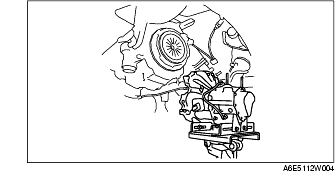
3. Remove the transaxle mounting bolts.
4. Remove the transaxle.
1. Set the transaxle on a jack and lift into place.
2. Install the transaxle mounting bolts.
3. Tighten the SST (49 E017 5A0) so that the engine is located at the specified position.
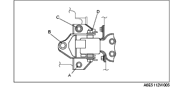
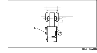
1. Verify that the engine mount rubbers are installed as shown.
2. By aligning the holes with the stud bolts, install the No.4 engine mount bracket to the transaxle.
3. By aligning the holes with the stud bolts, install the No.1 engine mount to the transaxle.
4. Align the hole of the No.4 engine mount bracket with the No.4 engine mount rubber on vehicle, and temporarily tighten the bolt D.
5. Tighten the nut B,C in order of B→C, then bolt A.
6. Tighten the bolt D.
7. Tighten the bolt D to the No.1 engine mount.
8. Remove the SST (49 E017 5A0).