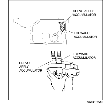
1. Install the accumulator springs and accumulators into the transaxle case.
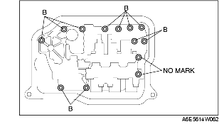
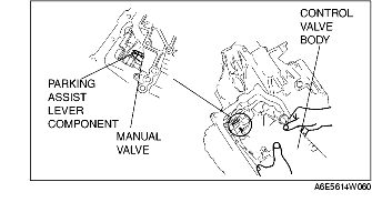
2. Install the control valve body component.
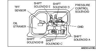
3. Install the oil strainer.
4. Match the harness colors, then connect the solenoid connector and TFT sensor connector.
|
Spring
|
Color of connector (harness side)
|
|---|---|
|
Pressure control solenoid
|
Black
|
|
Shift solenoid A
|
White
|
|
Shift solenoid B
|
Blue
|
|
Shift solenoid C
|
Green
|
|
Shift solenoid D
|
White
|
|
Shift solenoid E
|
Black
|
5. Install the ground.
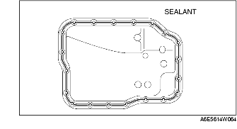
6. Apply a light coat of silicon sealant to the contact surfaces of the oil pan and transaxle case.
7. Install the oil pan.
8. Install the crossmember. (See FRONT CROSSMEMBER REMOVAL/INSTALLATION.)
9. Install the front tires and splash shield.
10. Install the under cover.
11. Connect the negative battery cable.
12. Add ATF and with the engine idling, inspect the ATF level. (See AUTOMATIC TRANSAXLE FLUID (ATF) REPLACEMENT [FN4A-EL].)
13. Carry out the mechanical system test. (See MECHANICAL SYSTEM TEST [FN4A-EL].)
14. Carry out the road test. (See ROAD TEST [FN4A-EL].)