MASTER WARNING LIGHT
id092200032400
Purpose
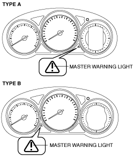
Type A instrument cluster
-
• The master warning light warns the driver that the instrument cluster has received a message from a related unit.
Type B instrument cluster
-
• The master warning light warns the driver that any of the following malfunctions is occurring.
-
― Brake switch malfunction
― Engine oil solenoid valve malfunction
― Power supply system malfunction
― Current sensor malfunction
― Global central configuration malfunction
― Timing chain malfunction (SKYACTIV-D 2.2)
― Blow-by heater malfunction (SKYACTIV-D 2.2)
― Power brake unit malfunction (SKYACTIV-D 2.2)
― Power brake unit vacuum sensor malfunction (SKYACTIV-D 2.2)
― Vacuum pump malfunction (SKYACTIV-D 2.2)
Function
Type A instrument cluster
-
• When the instrument cluster receives a message request signal from the related unit, the master warning light illuminates.
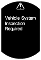
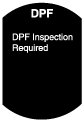
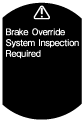
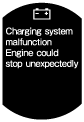
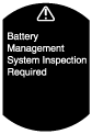
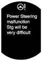
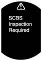
• The master warning light illuminates and the displayed messages in the LCD are as follows:
—:Not applicable
|
LCD
|
Related unit
|
Reference/function
|
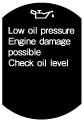 |
PCM
|
|
 |
PCM
|
|
 |
PCM
|
|
 |
PCM
|
|
 |
PCM
|
|
 |
PCM
|
|
 |
PCM
|
|
 |
EPS CM
|
|
 |
Laser sensor
|
|
 |
TCM
|
|
 |
Start stop unit (Keyless entry system/advanced keyless entry system)
|
|
 |
Vehicle Control Module (V/C-Module) (SBS (smart brake support))
|
|
 |
Vehicle Control Module (V/C-Module) (DRSS (Distance recognition support system))
|
|
-
• If the cancel procedure for preventing unnecessary operation of the brake override system is implemented, the PCM sends a master warning light flash request signal to the instrument cluster as a CAN signal. The instrument cluster flashes the master warning light based on the master warning light flash request signal sent from the PCM. For the cancel procedure to prevent unnecessary operation of the brake override system, refer to the
DRIVE-BY-WIRE CONTROL [SKYACTIV-G 2.0, SKYACTIV-G 2.5],
FUEL INJECTION AMOUNT CONTROL [SKYACTIV-D 2.2].
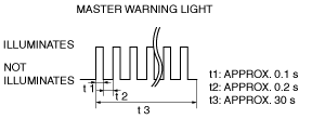
• The master warning light flashing pattern is as indicated in the figure.
• If the engine oil reset procedure is implemented after the engine oil has been replaced, the PCM sends a master warning light flash request signal to the instrument cluster as a CAN signal. The instrument cluster flashes the master warning light based on the master warning light flash request signal from the PCM.
• The master warning light flashing pattern is as indicated in the figure.
Type B instrument cluster
-
• The instrument cluster illuminates the master warning light based on the following CAN signals:
-
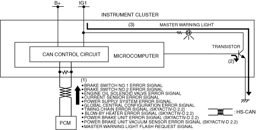
― Brake switch No.1 error signal, brake switch No.2 error signal, engine oil solenoid valve error signal, current sensor error signal, power supply system error signal, global central configuration error signal, timing chain error signal (SKYACTIV-D 2.2), power brake unit error signal (SKYACTIV-D 2.2), power brake unit vacuum sensor error signal (SKYACTIV-D 2.2), and blow-by heater error signal (SKYACTIV-D 2.2) sent from the PCM
-
Note
-
-
• If the cancel procedure for preventing unnecessary operation of the brake override system is implemented, the PCM sends a master warning light flash request signal to the instrument cluster as a CAN signal. The instrument cluster flashes the master warning light based on the master warning light flash request signal sent from the PCM. For the cancel procedure to prevent unnecessary operation of the brake override system, refer to the
DRIVE-BY-WIRE CONTROL [SKYACTIV-G 2.0, SKYACTIV-G 2.5],
FUEL INJECTION AMOUNT CONTROL [SKYACTIV-D 2.2].
• The master warning light flashing pattern is as indicated in the figure.
• If the engine oil reset procedure is implemented after the engine oil has been replaced, the PCM sends a master warning light flash request signal to the instrument cluster as a CAN signal. The instrument cluster flashes the master warning light based on the master warning light flash request signal from the PCM.
• The master warning light flashing pattern is as indicated in the figure.
Construction
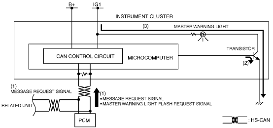
• The instrument cluster microcomputer controls the illumination/flashing/turning off of the master warning light based on each error signal sent from the PCM or a message request signal (Type A only) from the related system.
• The master warning light is set in the instrument cluster.
Operation
1. When the ignition is switched ON (engine off or on), the instrument cluster receives (1) each error signal or a master warning light flash request signal from the PCM, or a message request signal (Type A only) from the related unit.
2. The instrument cluster turns the transistor on (2) intermittently for flashing and continuously for illumination based on each signal.
3. The master warning light flashes (3) when the transistor is turned on intermittently, and it illuminates (3) when the transistor is turned on continuously.
Type A instrument cluster
Type B instrument cluster
Fail-safe
• Function not equipped.