|
ac5wzw00004286
AUTOMATIC TRANSAXLE REMOVAL/INSTALLATION [GW6A-EL]
id0517i21172i1
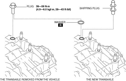
Replacement Part
|
washer
Quantity: 1
Location of use: plug
|
Removal
1. Disconnect the negative battery cable. (See NEGATIVE BATTERY CABLE DISCONNECTION/CONNECTION [SKYACTIV-D 2.2].)
2. Remove the air cleaner and air hose as a single unit. (See INTAKE-AIR SYSTEM REMOVAL/INSTALLATION [SKYACTIV-D 2.2].)
3. Remove the battery tray. (See BATTERY REMOVAL/INSTALLATION [SKYACTIV-D 2.2].)
4. Disconnect the wiring harness clip from the transaxle.
ac5wzw00004286
|
5. Remove the splash shield (LH). (See SPLASH SHIELD REMOVAL/INSTALLATION.)
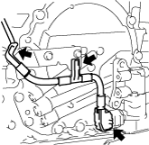
6. Disconnect the electric AT oil pump connector and electric AT oil pump harness from the transaxle.
ac5wzw00004287
|
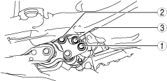
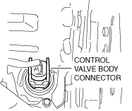
7. Disconnect the control valve body connector.
ac5wzw00004288
|
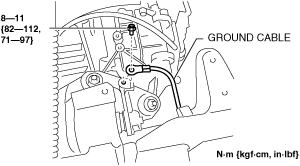
8. Disconnect the ground cable.
ac5wzw00004289
|
9. Disconnect the selector cable from the transaxle. (See AUTOMATIC TRANSAXLE SHIFT MECHANISM REMOVAL/INSTALLATION.)
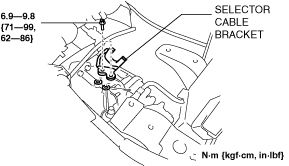
10. Remove the selector cable bracket.
ac5wzw00004291
|
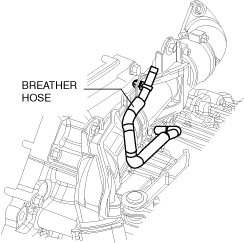
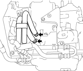
11. Remove the breather hose from the transaxle.
adejjw00004071
|
12. Remove the EGR cooler. (See EGR COOLER REMOVAL/INSTALLATION [SKYACTIV-D 2.2].)
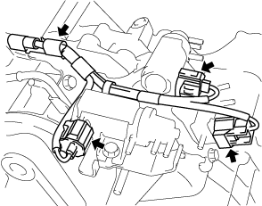
13. Disconnect the solenoid valve connectors and the wiring harness from the solenoid valve component. (See COMPRESSOR BYPASS SOLENOID VALVE REMOVAL/INSTALLATION [SKYACTIV-D 2.2]) (See REGULATING SOLENOID VALVE REMOVAL/INSTALLATION [SKYACTIV-D 2.2]) (See WASTEGATE SOLENOID VALVE REMOVAL/INSTALLATION [SKYACTIV-D 2.2])
ac5wzw00004292
|
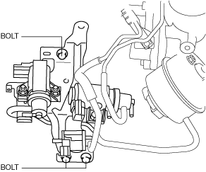
14. Disconnect the solenoid valve component from the ATX with the hose still connected, and set it out of the way. (See COMPRESSOR BYPASS SOLENOID VALVE REMOVAL/INSTALLATION [SKYACTIV-D 2.2]) (See REGULATING SOLENOID VALVE REMOVAL/INSTALLATION [SKYACTIV-D 2.2]) (See WASTEGATE SOLENOID VALVE REMOVAL/INSTALLATION [SKYACTIV-D 2.2])
ac5wzw00004293
|
15. Remove the joint cover. (See STEERING WHEEL AND COLUMN REMOVAL/INSTALLATION.)
16. Disconnect the intermediate shaft from the steering gear and linkage. (See STEERING WHEEL AND COLUMN REMOVAL/INSTALLATION.)
17. Remove the front tires. (See GENERAL PROCEDURES (SUSPENSION).)
18. Remove the front under cover No.2. (See FRONT UNDER COVER No.2 REMOVAL/INSTALLATION.)
19. Remove the front under cover No.1. (See FRONT UNDER COVER No.1 REMOVAL/INSTALLATION.)
20. Drain the ATF. (See AUTOMATIC TRANSAXLE FLUID (ATF) REPLACEMENT [GW6A-EL, GW6AX-EL].)
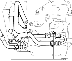
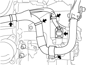
21. Disconnect the oil hose from the transaxle. (With oil cooler No.2) (See OIL COOLER REMOVAL/INSTALLATION [GW6A-EL, GW6AX-EL].)
ac5wzw00004294
|
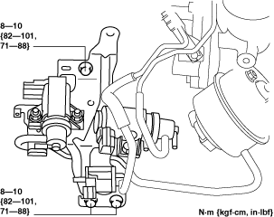
22. Set the oil pipe component in a place which does not interfere with the servicing. (With oil cooler No.2) (See OIL COOLER REMOVAL/INSTALLATION [GW6A-EL, GW6AX-EL].)
ac5wzw00004295
|
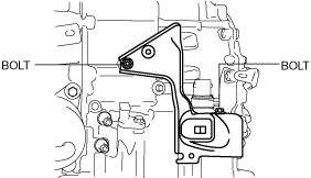
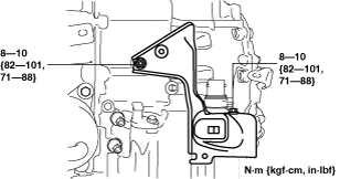
23. Remove the bracket from the transaxle.
ac5wzw00004296
|
24. Disconnect the oil cooler from the transaxle with the hose connected. (Except Automatic Transaxle Replacement) (See OIL COOLER REMOVAL/INSTALLATION [GW6A-EL, GW6AX-EL].)
25. Disconnect the water hose from the oil cooler. (Automatic Transaxle Replacement) (See OIL COOLER REMOVAL/INSTALLATION [GW6A-EL, GW6AX-EL].)
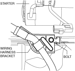
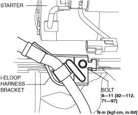
26. Disconnect the wiring harness bracket from the engine. (Vehicle with i-ELOOP)
adejjw00004069
|
27. Remove the starter. (See STARTER REMOVAL/INSTALLATION [SKYACTIV-D 2.2].)
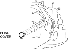
28. Remove the blind cover.
ac5wzw00004297
|
29. Hold the crankshaft pulley to prevent drive plate from rotating.
ac5wzw00004298
|
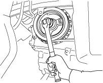
30. Remove the torque converter nuts from the starter installation hole.
ac5wzw00004299
|
31. Disconnect the front ABS wheel-speed sensors from the steering knuckles. (See FRONT ABS WHEEL-SPEED SENSOR REMOVAL/INSTALLATION.)
32. Disconnect the clips securing the brake hose from the front shock absorbers. (See BRAKE HOSE (FRONT) REMOVAL/INSTALLATION.)
33. Disconnect the tie-rod end ball joints from the steering knuckles. (See STEERING GEAR AND LINKAGE REMOVAL/INSTALLATION.)
34. Disconnect the front lower arms from the steering knuckles. (See FRONT LOWER ARM REMOVAL/INSTALLATION.)
35. Disconnect the front stabilizer control links from the front stabilizer. (See FRONT STABILIZER REMOVAL/INSTALLATION.)
36. Disconnect the front drive shaft (LH) from the transaxle. (See FRONT DRIVE SHAFT REMOVAL/INSTALLATION.)
37. Disconnect the front drive shaft (RH) from the transaxle. (See FRONT DRIVE SHAFT REMOVAL/INSTALLATION.)
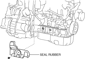
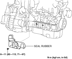
38. Remove the seal rubber.
ac5wzw00004300
|
39. Remove the front crossmember component and No.1 engine mount rubber as a single unit. (See FRONT CROSSMEMBER REMOVAL/INSTALLATION.)
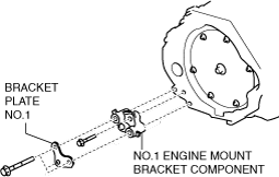
40. Remove the bracket plate No.1 and No.1 engine mount bracket component from the transaxle.
ac5wzw00004301
|
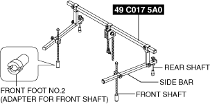
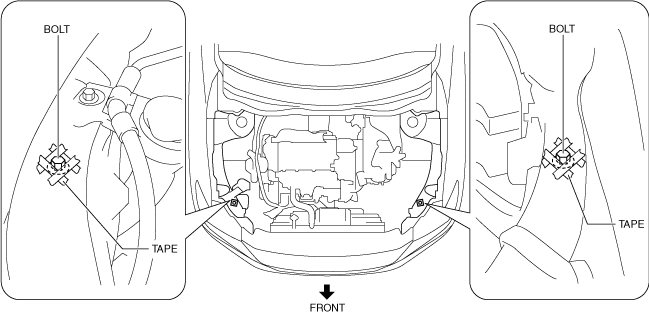
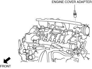
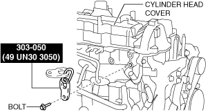
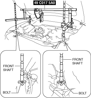
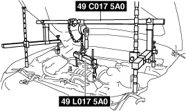
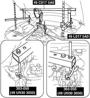
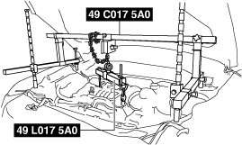
41. Install the SST using the following procedures.
am6zzw00010929
|
am6zzw00008971
|
am6zzw00010930
|
Engine front side
am6zzw00010812
|
Engine rear side
am6zzw00010813
|
am6zzw00008972
|
am6zzw00008973
|
am6zzw00008974
|
am6zzw00008975
|
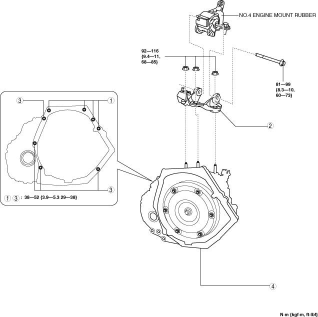
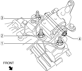
42. Remove in the order shown in the figure.
ac5wzw00004311
|
|
1
|
Transaxle mounting bolts (upper side)
|
|
2
|
No.4 engine mount bracket
|
|
3
|
Transaxle mounting bolts (lower side)
|
|
4
|
Transaxle
|
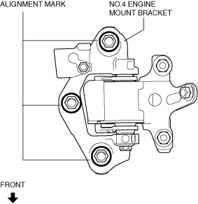
No.4 engine mount bracket removal note
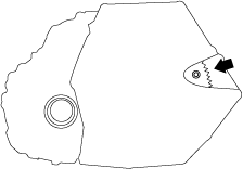
1. Place alignment marks on the locations shown in the figure so that they can be assembled to the same positions as before removal.
ac5wzw00004312
|
2. Remove the No.4 engine mount bracket.
Transaxle mounting bolt removal note
1. Adjust the SST and lean the engine toward the transaxle.
ac5wzw00004313
|
2. Support the transaxle on a jack.
ac5wzw00004314
|
3. Remove the transaxle mounting bolts (lower side).
4. Remove the transaxle.
Installation
1. If the transaxle is replaced with a new one, perform the following procedure.
ac9uuw00011693
|
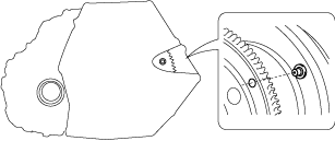
2. Verify that the torque converter stud bolts are inserted into the drive plate bolt holes from the starter installation hole.
ac5wzw00004315
|
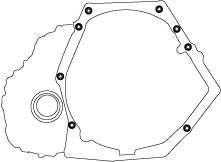
3. Install the transaxle mounting bolts.
ac5wzw00004316
|
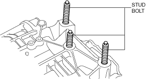
4. Tighten the stud bolts for the transaxle.
ac5wzw00004317
|
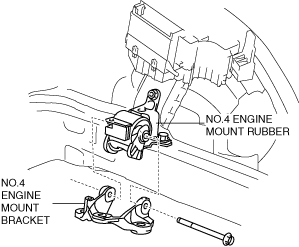
5. Install the No.4 engine mount bracket to No.4 engine mount rubber, and temporarily tighten the installation bolt.
ac5wzw00004318
|
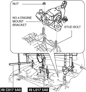
6. Pull up the transaxle using the SSTs, pass the transaxle stud bolts through the No.4 engine mount bracket, and temporarily tighten the No.4 engine mount installation nuts.
am6zzw00008976
|
7. Install the No.1 engine mount bracket component and the bracket plate No.1 to the transaxle, and temporarily tighten the installation bolts.
am6zzw00008977
|
8. Install the front crossmember component and No.1 engine mount rubber as a single unit. (See FRONT CROSSMEMBER REMOVAL/INSTALLATION.)
9. Temporarily tighten the No.1 engine mount rubber installation bolts.
ac5wzw00004321
|
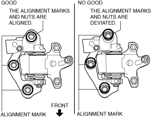
10. Align the alignment marks on the No.4 engine mount bracket and nuts, and temporarily tighten the nuts shown in the figure.
ac5wzw00004322
|
11. Tighten the No.4 engine mount bracket installation nuts and bolt in the order shown in the figure.
ac5wzw00004323
|
|
No. |
Tightening torque |
|---|---|
|
1, 2, 3
|
92—116 N·m {9.4—11 kgf·m, 69—85 ft·lbf}
|
|
4
|
81—99 N·m {8.3—10 kgf·m, 60—73 ft·lbf}
|
12. Tighten the No.1 engine mount bracket and bracket plate installation bolts in the order shown in the figure.
ac5wzw00004324
|
13. Tighten the No.1 engine mount rubber installation bolts in the order shown in the figure.
ac5wzw00004325
|
|
No. |
Tightening torque |
|---|---|
|
1
|
130—151 N·m {14—15 kgf·m, 96—111 ft·lbf}
|
|
2
|
130—164 N·m {14—16 kgf·m, 96—120 ft·lbf}
|
14. Remove the SST (49 C017 5A0, 49 L017 5A0).
15. Fix the crankshaft pulley to lock the torque converter against rotation.
ac5wzw00004326
|
16. Tighten the torque converter installation nuts.
ac5wzw00004327
|
17. Install the blind cover.
ac5wzw00004328
|
18. Install the starter. (See STARTER REMOVAL/INSTALLATION [SKYACTIV-D 2.2].)
19. Install the wiring harness bracket to the engine. (Vehicle with i-ELOOP)
adejjw00004070
|
20. Install the seal rubber.
ac5wzw00004329
|
21. Install the front drive shaft (RH) to the transaxle. (See FRONT DRIVE SHAFT REMOVAL/INSTALLATION.)
22. Install the front drive shaft (LH) to the transaxle. (See FRONT DRIVE SHAFT REMOVAL/INSTALLATION.)
23. Install the front stabilizer control links to the front stabilizer. (See FRONT STABILIZER REMOVAL/INSTALLATION.)
24. Install the front lower arms to the steering knuckles. (See FRONT LOWER ARM REMOVAL/INSTALLATION.)
25. Install the tie-rod end ball joints to the steering knuckles. (See STEERING GEAR AND LINKAGE REMOVAL/INSTALLATION.)
26. Install the clips securing the brake hose to the front shock absorbers. (See BRAKE HOSE (FRONT) REMOVAL/INSTALLATION.)
27. Install the front ABS wheel-speed sensors to the steering knuckles. (See FRONT ABS WHEEL-SPEED SENSOR REMOVAL/INSTALLATION.)
28. Connect the water hose to the oil cooler. (Automatic Transaxle Replacement) (See OIL COOLER REMOVAL/INSTALLATION [GW6A-EL, GW6AX-EL].)
29. Install the oil cooler to the transaxle with the hose connected. (Except Automatic Transaxle Replacement) (See OIL COOLER REMOVAL/INSTALLATION [GW6A-EL, GW6AX-EL].)
30. Install the bracket to the transaxle.
ac5wzw00004330
|
31. Install the oil pipe component. (With oil cooler No.2) (See OIL COOLER REMOVAL/INSTALLATION [GW6A-EL, GW6AX-EL].)
ac5wzw00004331
|
32. Connect the oil hose to the transaxle. (With oil cooler No.2) (See OIL COOLER REMOVAL/INSTALLATION [GW6A-EL, GW6AX-EL].)
ac5wzw00004332
|
33. Install the front under cover No.1. (See FRONT UNDER COVER No.1 REMOVAL/INSTALLATION.)
34. Install the front tires. (See GENERAL PROCEDURES (SUSPENSION).)
35. Install the intermediate shaft to the steering gear and linkage. (See STEERING WHEEL AND COLUMN REMOVAL/INSTALLATION.)
36. Install the joint cover. (See STEERING WHEEL AND COLUMN REMOVAL/INSTALLATION.)
37. Install the solenoid valve component. (See COMPRESSOR BYPASS SOLENOID VALVE REMOVAL/INSTALLATION [SKYACTIV-D 2.2]) (See REGULATING SOLENOID VALVE REMOVAL/INSTALLATION [SKYACTIV-D 2.2]) (See WASTEGATE SOLENOID VALVE REMOVAL/INSTALLATION [SKYACTIV-D 2.2])
ac5wzw00004333
|
38. Connect the solenoid valve connectors and the wiring harness to the solenoid valve component. (See COMPRESSOR BYPASS SOLENOID VALVE REMOVAL/INSTALLATION [SKYACTIV-D 2.2]) (See REGULATING SOLENOID VALVE REMOVAL/INSTALLATION [SKYACTIV-D 2.2]) (See WASTEGATE SOLENOID VALVE REMOVAL/INSTALLATION [SKYACTIV-D 2.2])
ac5wzw00004334
|
39. Install the EGR cooler. (See EGR COOLER REMOVAL/INSTALLATION [SKYACTIV-D 2.2].)
40. Install the breather hose to the transaxle.
adejjw00004071
|
41. Install the selector cable bracket.
ac5wzw00004335
|
42. Connect the selector cable to the transaxle. (See AUTOMATIC TRANSAXLE SHIFT MECHANISM REMOVAL/INSTALLATION.)
43. Install the ground cable.
ac5wzw00004337
|
44. Connect the control valve body connector.
ac5wzw00004338
|
45. Connect the electric AT oil pump connector and electric AT oil pump harness to the transaxle.
ac5wzw00004339
|
46. Install the splash shield (LH). (See SPLASH SHIELD REMOVAL/INSTALLATION.)
47. Connect the wiring harness from the transaxle.
ac5wzw00004340
|
48. Install the battery tray. (See BATTERY REMOVAL/INSTALLATION [SKYACTIV-D 2.2].)
49. Install the air cleaner and air hose as a single unit. (See INTAKE-AIR SYSTEM REMOVAL/INSTALLATION [SKYACTIV-D 2.2].)
50. Disconnect the negative battery cable. (See NEGATIVE BATTERY CABLE DISCONNECTION/CONNECTION [SKYACTIV-D 2.2].)
51. Add the ATF. (See AUTOMATIC TRANSAXLE FLUID (ATF) REPLACEMENT [GW6A-EL, GW6AX-EL].)
52. Perform the “TCM configuration”. (automatic transaxle Replacement). (See TCM CONFIGURATION [GW6A-EL, GW6AX-EL].)
53. Perform the “Initial Learning” (automatic transaxle Replacement). (See INITIAL LEARNING [GW6A-EL, GW6AX-EL].)
54. Perform the “Mechanical System Test”. (See MECHANICAL SYSTEM TEST [GW6A-EL, GW6AX-EL].)
55. Install the front under cover No.2. (See FRONT UNDER COVER No.2 REMOVAL/INSTALLATION.)