 |
am6zzw00009166
STEERING WHEEL AND COLUMN REMOVAL/INSTALLATION
id061300801400
1. Remove the following parts:
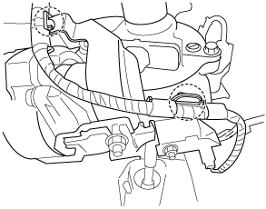
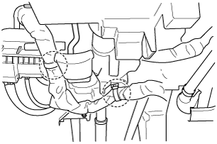
2. Detach the harness clips shown in the figure.
Without Lane-Keep Assist System
am6zzw00009166
|
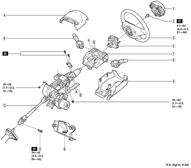
With Lane-Keep Assist System
am3uuw00011065
|
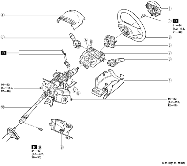
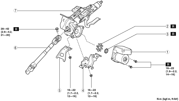
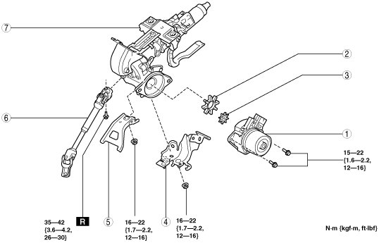
3. Remove in the order indicated in the table.
4. Install in the reverse order of removal.
5. If the EPS CM is replaced, perform the following procedure.
Without Lane-Keep Assist System
am6zzw00013427
|
|
1
|
Driver-side air bag module
|
|
2
|
Lockbolt
|
|
3
|
Steering wheel
(See Steering Wheel Removal Note.)
|
|
4
|
Column cover
|
|
5
|
Clock spring
|
|
6
|
Light switch, wiper and washer switch
|
|
7
|
Start stop unit
|
|
8
|
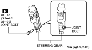
Joint cover
|
|
9
|
Joint bolt
|
|
10
|
Steering column component
|
am6zzw00009168
|
|
1
|
EPS CM
(See EPS CM Removal Note.)
|
|
2
|
Rubber
|
|
3
|
Spacer
|
|
4
|
Harness bracket
|
|
5
|
Bracket (MTX vehicles)
(See Bracket Installation Note.)
|
|
6
|
Intermediate shaft
|
|
7
|
Steering column
|
With Lane-Keep Assist System
am6zzw00013428
|
|
1
|
Driver-side air bag module
|
|
2
|
Lockbolt
|
|
3
|
Steering wheel
(See Steering Wheel Removal Note.)
|
|
4
|
Column cover
|
|
5
|
Clock spring
|
|
6
|
Light switch, wiper and washer switch
|
|
7
|
Start stop unit
|
|
8
|
Joint cover
|
|
9
|
Joint bolt
|
|
10
|
Steering column component
|
am6zzw00013429
|
|
1
|
EPS CM
(See EPS CM Removal Note.)
|
|
2
|
Rubber
|
|
3
|
Spacer
|
|
4
|
Harness bracket
|
|
5
|
Bracket (MTX vehicles)
(See Bracket Installation Note.)
|
|
6
|
Intermediate shaft
|
|
7
|
Steering column
|
Steering Wheel Removal Note
1. Set the vehicle wheels in the straight-ahead position.
2. Remove the steering wheel using any commercially available puller.
Steering Column Component Removal Note
1. Lock the adjusting lever.
2. Remove the bolt, disconnect the intermediate shaft from the steering gear (pinion shaft).
3. Remove the nut, and then remove the steering column component from the dashboard member.
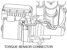
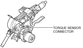
EPS CM Removal Note
1. Disconnect the torque sensor connector (EPS CM side).
Without Lane-Keep Assist System
am6zzw00009169
|
With Lane-Keep Assist System
am6zzw00012925
|
2. Remove the EPS CM.
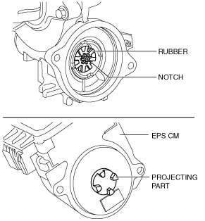
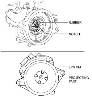
Spacer, Rubber and EPS CM Installation Note
1. Install the spacer and rubber to the steering column.
2. Install the EPS CM so that the projecting part of the EPS CM (rotor) is engaged with the notch in the rubber.
Without Lane-Keep Assist System
am6zzw00013063
|
With Lane-Keep Assist System
am6zzw00012926
|
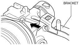
Bracket Installation Note
1. Insert the bracket bolt into the steering column and install the projecting part of the bracket to the installation area of the steering column.
ac5wzw00000333
|
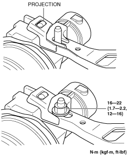
2. Verify that the projection on the steering column is inserted into the hole in the bracket as shown in the figure and tighten the nut to the specified torque.
ac5wzw00001028
|
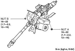
Steering Column Component Installation Note
1. Temporarily install the steering column component to the dashboard member using nuts A and B.
am6zzw00009170
|
2. Tighten the nuts in the order of nut A and nut B.
3. Insert the intermediate shaft into the steering gear (pinion shaft) to the position shown in the figure, and tighten it using a new bolt.
am6zzw00013430
|
Steering Wheel Installation Note
1. Set the vehicle wheels in the straight-ahead position, and install the steering wheel using a new lockbolt.