|
1
|
INSPECT DRIVER-SIDE AIR BAG MODULE CONNECTOR
-
Warning
-
• Handling the component parts improperly can accidentally operate (deploy) the air bag module, which may seriously injure you. Read the service warnings/cautions and the workshop manual before handling the air bag system components.
• Switch the ignition to off.
• Inspect the clock spring connector. (Corrosion, damage, and disconnected pins)
• Is there any malfunction of the clock spring connector?
|
Yes
|
Then go to Step 7.
|
|
No
|
Go to the next step.
|
|
2
|
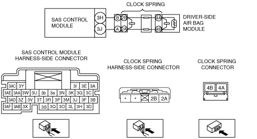
INSPECT CLOCK SPRING
• Remove the steering wheel.
• Inspect for continuity between clock spring connector terminals 2B—4A and 2A—4B.
-
Note
-
• Inspect the clock spring wiring harness for continuity while shaking it.
• Is there continuity?
|
Yes
|
Go to the next step.
|
|
No
|
Then go to Step 7.
|
|
3
|
INSPECT DRIVER-SIDE AIR BAG MODULE CIRCUIT FOR SHORT TO GROUND
• Inspect for continuity between the following terminals (wiring harness-side) and body ground:
-
― SAS control module terminal 3H
― SAS control module terminal 3J
-
Note
-
• Inspect for continuity while shaking the wiring harness between the SAS control module and clock spring.
• Is there continuity?
|
Yes
|
Replace the wiring harness for a possible short to ground, then go to Step 7.
|
|
No
|
Go to the next step.
|
|
4
|
INSPECT DRIVER-SIDE AIR BAG MODULE CIRCUIT FOR OPEN CIRCUIT
• SAS control module and clock spring connectors are disconnected.
• Inspect for continuity between the following terminals (wiring harness-side):
-
― Clock spring terminal B—SAS control module terminal 3H
― Clock spring terminal A—SAS control module terminal 3J
-
Note
-
• Inspect for continuity while shaking the wiring harness between the SAS control module and clock spring.
• Is there continuity?
|
Yes
|
Go to the next step.
|
|
No
|
Replace the wiring harness for a possible open circuit, then go to Step 7.
|
|
5
|
INSPECT DRIVER-SIDE AIR BAG MODULE CIRCUIT FOR SHORT TO POWER SUPPLY
• SAS control module and clock spring connectors are disconnected.
• Switch the ignition ON (engine off or on).
• Measure the voltage at the following terminals (wiring harness-side):
-
― SAS control module terminal 3H
― SAS control module terminal 3J
-
Note
-
• Measure the voltage while shaking the wiring harness between the SAS control module and clock spring.
• Is the voltage 0 V?
|
Yes
|
Go to the next step.
|
|
No
|
Replace the wiring harness for a possible short to power supply, then go to Step 7.
|
|
6
|
INSPECT DRIVER-SIDE AIR BAG MODULE
• Switch the ignition to off.
• Connect the SAS control module connectors.
• Except for the driver-side air bag module connector, reconnect all disconnected connectors.
• Connect the SST (Fuel and thermometer checker) or apply 2 ohms resistance to the clock spring connector terminals 4A and 4B.
• Set the SST (Fuel and thermometer checker) to 2 ohms.
• Switch the ignition ON (engine off or on).
• Are the same DTCs present?
|
Yes
|
Go to the next step.
|
|
No
|
Replace the driver-side air bag module. (See DRIVER-SIDE AIR BAG MODULE REMOVAL/INSTALLATION.) Then go to the next step.
|
|
7
|
PERFORM SAS CONTROL MODULE DTC INSPECTION
• Switch the ignition to off.
• Disconnect the SST (Fuel and thermometer checker) or the 2 ohms resistance.
• Connect the driver-side air bag module connector.
• Switch the ignition ON (engine off or on).
• Are the same DTCs present?
|
Yes
|
Replace the SAS control module. (See SAS CONTROL MODULE REMOVAL/INSTALLATION.) |
|
No
|
DTC troubleshooting completed.
|