-
• If the valve clearance is out of the standard value, adjust it. (See VALVE CLEARANCE ADJUSTMENT [L8, LF, L5].)
am3zzw00002420
|
-
Valve clearance [Engine cold]
-
IN: 0.22—0.28 mm {0.009—0.011 in}EX: 0.27—0.33 mm {0.011—0.012 in}
VALVE CLEARANCE INSPECTION [L8, LF, L5]
id0110a6803400
1. Disconnect the negative battery cable.
2. Remove the plug hole plate. (See PLUG HOLE PLATE REMOVAL/INSTALLATION [L8, LF, L5].)
3. Remove the ignition coils. (See IGNITION COIL REMOVAL/INSTALLATION [L8, LF, L5].)
4. Remove the ventilation hose. (See INTAKE-AIR SYSTEM REMOVAL/INSTALLATION [L8, LF, L5].)
5. Disconnect the camshaft position (CMP) sensor connector.
6. Disconnect the oil control valve (OCV) connector. (With variable valve timing mechanism.)
7. Remove the cylinder head cover. (See TIMING CHAIN REMOVAL/INSTALLATION [L8, LF, L5].)
8. Set the front mudguard (RH) out of the way. (See FRONT MUDGUARD REMOVAL/INSTALLATION.)
9. Remove the splash shield (RH).
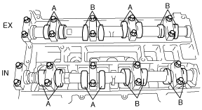
10. Measure the valve clearance.
am3zzw00002420
|
am3zzw00002420
|
11. Install the splash shield (RH).
12. Install the front mudguard (RH). (See FRONT MUDGUARD REMOVAL/INSTALLATION.)
13. Install the cylinder head cover. (See TIMING CHAIN REMOVAL/INSTALLATION [L8, LF, L5].)
14. Connect the OCV connector. (With variable valve timing mechanism.)
15. Connect the CMP sensor connector.
16. Install the ventilation hose. (See INTAKE-AIR SYSTEM REMOVAL/INSTALLATION [L8, LF, L5].)
17. Install the ignition coils. (See IGNITION COIL REMOVAL/INSTALLATION [L8, LF, L5].)
18. Install the plug hole plate. (See PLUG HOLE PLATE REMOVAL/INSTALLATION [L8, LF, L5].)
19. Connect the negative battery cable.