 |
am6zzw00002589
VARIABLE VALVE TIMING ACTUATOR INSPECTION [LF, L5]
id0110a7801200
1. Disconnect the negative battery cable.
2. Remove the plug hole plate. (See PLUG HOLE PLATE REMOVAL/INSTALLATION [L8, LF, L5].)
3. Remove the ignition coils. (See IGNITION COIL REMOVAL/INSTALLATION [L8, LF, L5].)
4. Remove the ventilation hose. (See INTAKE-AIR SYSTEM REMOVAL/INSTALLATION [L8, LF, L5].)
5. Disconnect the camshaft position (CMP) sensor connector.
6. Disconnect the oil control valve (OCV) connector.
7. Remove the cylinder head cover. (See TIMING CHAIN REMOVAL/INSTALLATION [L8, LF, L5].)
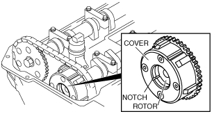
8. Confirm that notch of the rotor and notch of the cover at the variable valve timing actuator are aligned and fitted.
am6zzw00002589
|
9. Install the cylinder head cover. (See TIMING CHAIN REMOVAL/INSTALLATION [L8, LF, L5].)
10. Connect the OCV connector.
11. Connect the CMP sensor connector.
12. Install the ventilation hose. (See INTAKE-AIR SYSTEM REMOVAL/INSTALLATION [L8, LF, L5].)
13. Install the ignition coils. (See IGNITION COIL REMOVAL/INSTALLATION [L8, LF, L5].)
14. Install the plug hole plate. (See PLUG HOLE PLATE REMOVAL/INSTALLATION [L8, LF, L5].)
15. Connect the negative battery cable.