|
am6zzw00000222
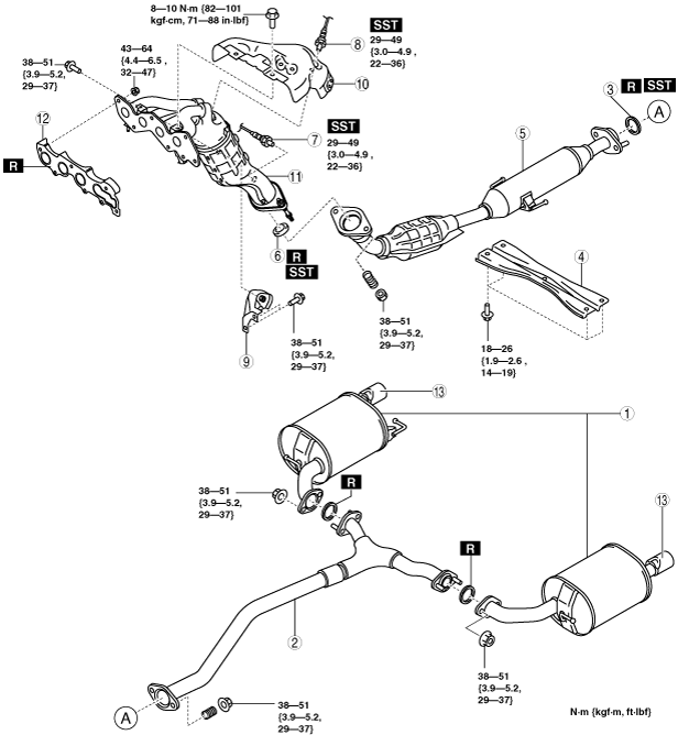
EXHAUST SYSTEM REMOVAL/INSTALLATION [L8, LF, L5]
id0115a5800200
1. Disconnect the negative battery cable.
2. Remove the plug hole plate. (See PLUG HOLE PLATE REMOVAL/INSTALLATION [L8, LF, L5].)
3. Remove in the order indicated in the table.
4. Remove the insulator. (See Exhaust System Insulator Removal/installation Note.)
5. Install in the reverse order of removal.
L8, LF
am6zzw00000222
|
|
1
|
Main silencer
|
|
2
|
Middle pipe
|
|
3
|
Seal ring (rear side)
(See Seal Ring Removal Note.)
|
|
4
|
Tunnel member
|
|
5
|
HO2S
|
|
6
|
A/F sensor
|
|
7
|
TWC
(See TWC Removal Note)
|
|
8
|
Seal ring (front side)
(See Seal Ring Removal Note.)
|
|
9
|
Exhaust manifold bracket
|
|
10
|
Exhaust manifold upper insulator
|
|
11
|
Exhaust manifold
|
|
12
|
Exhaust manifold gasket
|
|
13
|
Exhaust manifold lower insulator
|
|
14
|
Tailpipe garnish
|
L5
am6zzw00004500
|
|
1
|
Main silencer
|
|
2
|
Middle pipe
|
|
3
|
Seal ring (rear side)
(See Seal Ring Removal Note.)
|
|
4
|
Tunnel member
|
|
5
|
TWC
(See TWC Removal Note)
|
|
6
|
Seal ring (front side)
(See Seal Ring Removal Note.)
|
|
7
|
HO2S
|
|
8
|
A/F sensor
|
|
9
|
Exhaust manifold bracket
|
|
10
|
Exhaust manifold upper insulator
|
|
11
|
Exhaust manifold
|
|
12
|
Exhaust manifold gasket
|
|
13
|
Tailpipe garnish
|
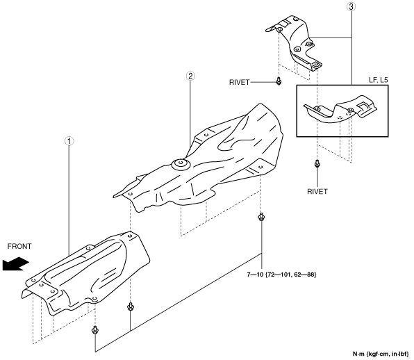
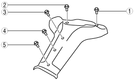
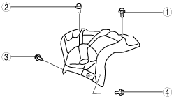
Exhaust System Insulator Removal/installation Note
1. Remove the exhaust system insulator in the order shown in the figure.
2. Install in the reverse order of removal.
am6zzw00004501
|
|
1
|
Insulator (front)
|
|
2
|
Insulator (middle)
|
|
3
|
Insulator (rear)
|
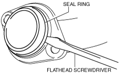
Seal Ring Removal Note
1. Remove the seal ring using a flathead screwdriver being careful not to damage the pipe.
am6zzw00000228
|
TWC Removal Note
1. Remove the aerodynamic under cover No.2. (See AERODYNAMIC UNDER COVER NO.2 REMOVAL/INSTALLATION.)
2. Remove the TWC.
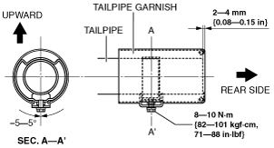
Tailpipe Garnish Replacement Note
1. Remove the spot welding on the damaged tailpipe garnish.
2. Install a new tailpipe garnish as shown in the figure.
am6zzw00003843
|
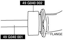
Flange Surface Installation Note
1. Sand the surface shown in the figure using sandpaper and remove sanding residue, accumulated matter, and friction marks.
2. Degrease the sanded surface.
am6zzw00011898
|
Exhaust Manifold Installation Note
1. Temporarily tighten the exhaust manifold installation nuts.
2. Tighten the exhaust manifold installation nuts in the order shown in the figure.
am6zzw00000225
|
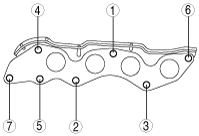
Exhaust Manifold Upper Insulator Installation Note (L8, LF)
1. Temporarily tighten the exhaust manifold insulator.
2. Tighten the exhaust manifold insulator in the order shown in the figure.
am6zzw00000226
|
Exhaust Manifold Upper Insulator Installation Note (L5)
1. Temporarily tighten the exhaust manifold insulator.
2. Tighten the exhaust manifold insulator in the order shown in the figure.
am6zzw00000227
|
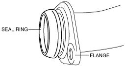
Seal Ring (Front Side) Installation Note
1. Temporarily install the seal ring to the pipe so that the seal ring is even with the flange.
am6zzw00000861
|
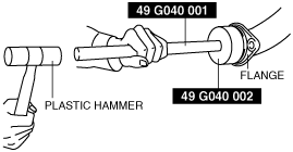
2. Install the SST to the seal ring so that the SST is even with the flange.
am6zzw00000862
|
3. Press in the seal ring by tapping the SST using a plastic hammer until the seal ring contacts the flange.
am6zzw00000863
|
Seal Ring (Rear Side) Installation Note
1. Temporarily install the seal ring to the pipe so that the seal ring is even with the flange.
am6zzw00000229
|
2. Install the SST to the seal ring so that the SST is even with the flange.
am6zzw00000230
|
3. Press in the seal ring by tapping the SST using a plastic hammer until the seal ring contacts the flange.
am6zzw00000231
|