1. Connect the M-MDS to the DLC-2.
am6zzw00000266
|

2. Using the simulation function “FP”, start the fuel pump. (See ON-BOARD DIAGNOSTIC TEST [L8, LF, L5].)
FUEL TANK REMOVAL/INSTALLATION [L8, LF, L5]
id0114a5801600
1. Level the vehicle.
2. Complete the “BEFORE SERVICE PRECAUTION”. (See BEFORE SERVICE PRECAUTION [L8, LF, L5].)
3. Disconnect the quick release connector (engine compartment, fuel distributor side). (See QUICK RELEASE CONNECTOR REMOVAL/INSTALLATION [L8, LF, L5].)
4. Connect a long hose to the disconnected quick release connector and drain the fuel into a container used for collecting gasoline.
5. Drain the fuel from the fuel tank using the following procedure:
am6zzw00000266
|
am6zzw00000293
|
am6zzw00000268
|
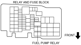
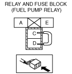
6. Stop the fuel pump using the following procedure.
7. Remove the middle pipe. (See EXHAUST SYSTEM REMOVAL/INSTALLATION [L8, LF, L5].)
8. Remove the floor under cover. (See FLOOR UNDER COVER REMOVAL/INSTALLATION.)
9. Remove the rear trailing link under cover. (See REAR TRAILING LINK REMOVAL/INSTALLATION.)
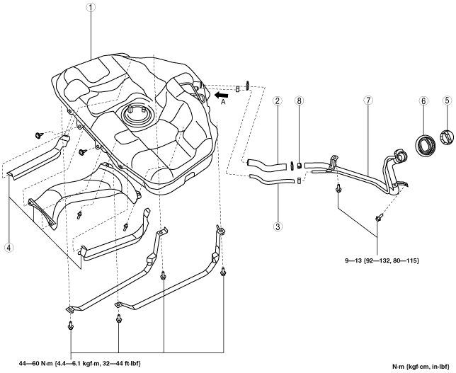
10. Remove in the order indicated in the table.
11. Install in the reverse order of removal.
12. Complete the “AFTER SERVICE PRECAUTION”. (See AFTER SERVICE PRECAUTION [L8, LF, L5].)
am6zzw00000269
|
|
1
|
Fuel tank
|
|
2
|
Joint hose
(See Joint Hose Installation Note.)
|
|
3
|
Breather hose
|
|
4
|
Insulator
(See Rivet Removal Note.)
|
|
5
|
Fuel-filler cap
|
|
6
|
Dust cover
|
|
7
|
Fuel-filler pipe
|
|
8
|
Nonreturn valve
|
Fuel Tank Component Removal Note
1. Remove the rear seat cushion. (4SD) (See REAR SEAT CUSHION REMOVAL/INSTALLATION [4SD].)
2. Lift up the rear seat cushion. (5HB) (See REAR SEAT REMOVAL/INSTALLATION [5HB/WAGON].)
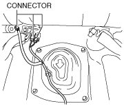
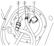
3. Disconnect the connectors shown in the figure.
am6zzw00000867
|
4. Remove the service hole cover.
5. Disconnect the following parts shown in the figure.
am6zzw00000334
|
6. Remove the fuel tank component.
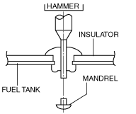
Rivet Removal Note
1. Push out the mandrel using a hammer and punch (2—2.8 mm {0.08—0.11 in} diameter).
am6zzw00000284
|
2. Remove the flange using a drill (5 mm {0.20 in} drill bit).
am6zzw00000285
|
Fuel-Filler Pipe Removal Note
1. Remove the rear tire (LH). (WGN)
2. Remove the fuel-filler pipe.
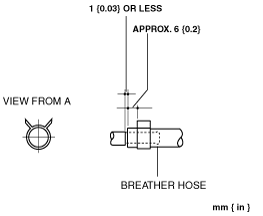
Breather Hose Installation Note
1. Install the breather hose and clip as shown in the figure.
am6zzw00000272
|
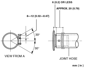
Joint Hose Installation Note
1. Install the joint hose and clamp as shown in the figure.
am6zzw00000273
|