 |
am6zzw00004801
FRONT LOWER ARM REMOVAL/INSTALLATION
id021300800600
1. Remove the under cover.
2. When working on the right side of the vehicle, remove the front auto leveling sensor. (Vehicle with discharge headlight system) (See AUTO LEVELING SENSOR REMOVAL/INSTALLATION.)
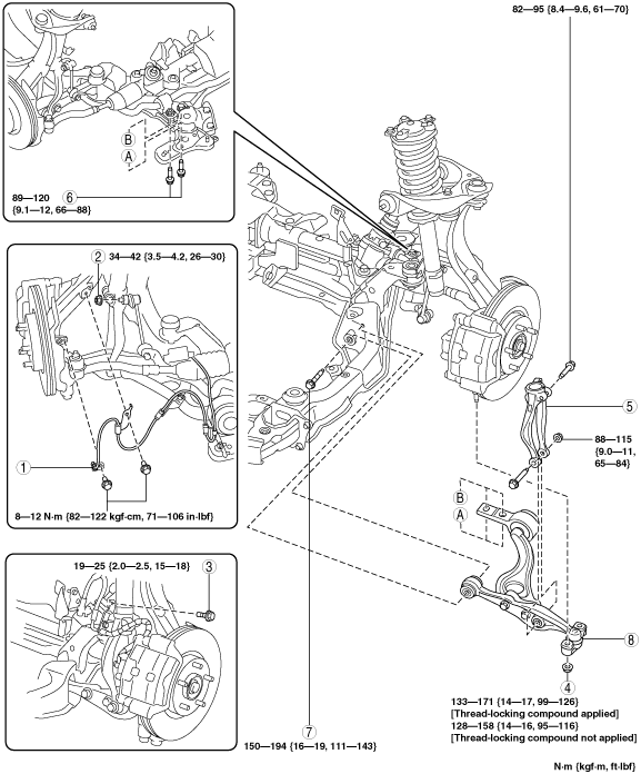
3. Remove in the order indicated in the table.
4. Install in the reverse order of removal.
5. Inspect for front wheel alignment. (See FRONT WHEEL ALIGNMENT [European (L.H.D., U.K.) Specs.].)(See FRONT WHEEL ALIGNMENT [Australian Specs. and General (L.H.D., R.H.D.) Specs.].)
am6zzw00004801
|
|
1
|
Front ABS wheel-speed sensor
|
|
2
|
Front stabilizer control link upper side nut
|
|
3
|
Brake hose bracket bolt
|
|
4
|
Front lower arm outer side nut
|
|
5
|
Damper fork
|
|
6
|
Front lower arm inner side bolt (rear)
|
|
7
|
Front lower arm inner side bolt (front)
|
|
8
|
Front lower arm
|
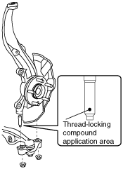
Front Lower Arm Outer Side Nut Removal Note
Front Lower Arm Outer Side Nut Installation Note
1. Visually verify the stud bolt of the knuckle and identify if thread-locking compound is applied to the stud bolt or not.
am6zzw00004805
|
2. Tighten the front lower arm outer side nut.
Front Lower Arm Inner Side Bolt (Front) Removal Note [FS5A-EL]
1. Slightly bend back the mudguard (LH/RH).
2. Remove the fastener installing the splash shield (LH/RH) to the front crossmember.
am6zzw00002414
|
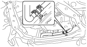
3. Remove the radiator hose bracket bolt.
am6zzw00001955
|
4. Detach the extension.
am6zzw00001958
|
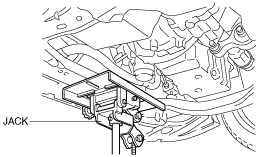
5. Support the crossmember component with a jack.
am6zzw00002416
|
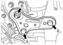
6. Remove the crossmember bracket bolts A and loosen the crossmember nut B.
am6zzw00002415
|
7. Loosen the nuts for the middle crossmember.
8. Remove the nuts at the front of the crossmember.
9. Lower the jack gradually and tilt the crossmember towards the front.
10. Remove the lower arm inner side bolt (front).