 |
am6zzw00001515
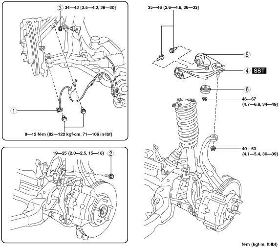
FRONT UPPER ARM REMOVAL/INSTALLATION
id021300801900
1. When working on the right side of the vehicle, disconnect the front auto leveling sensor link. (Vehicle with discharge headlight systems) (See AUTO LEVELING SENSOR REMOVAL/INSTALLATION.)
2. Remove in the order indicated in the table.
3. Install in the reverse order of removal.
4. Inspect the front wheel alignment. (See FRONT WHEEL ALIGNMENT [European (L.H.D., U.K.) Specs.].)(See FRONT WHEEL ALIGNMENT [Australian Specs. and General (L.H.D., R.H.D.) Specs.].)
am6zzw00001515
|
|
1
|
Front ABS wheel-speed sensor
|
|
2
|
Brake hose bracket bolt
|
|
3
|
Front stabilizer control link upper side nut
|
|
4
|
Front upper arm ball joint
|
|
5
|
Front upper arm
(See Front Upper Arm Removal Note.)
|
|
6
|
Dynamic damper
|
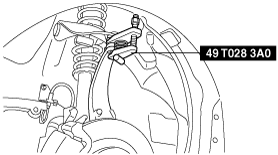
Front Upper Arm Ball Joint Removal Note
1. Support the knuckle using the jack.
2. Separate the ball joint from the knuckle using the SST.
am6zzw00001951
|
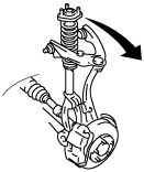
Front Upper Arm Removal Note
1. Remove the nuts from the upper part of the front shock absorber.
2. Pull the front shock absorber and coil spring out of the way, towards the outer side of the vehicle.
am6zzw00001227
|
3. Remove the bolts.
4. Remove the front upper arm.