|
am6zzw00003365
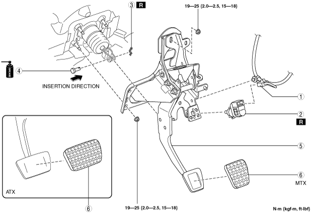
BRAKE PEDAL REMOVAL/INSTALLATION
id041100193300
1. Remove the accelerator pedal. (See ACCELERATOR PEDAL REMOVAL/INSTALLATION [L8, LF, L5].) (See ACCELERATOR PEDAL COMPONENT REMOVAL/INSTALLATION [MZR-CD (RF Turbo)].) (See ACCELERATOR PEDAL COMPONENT REMOVAL/INSTALLATION [MZR-CD 2.2].)
2. Remove the parking sensor control module. (L.H.D. (with parking sensor)) (See PARKING SENSOR CONTROL MODULE REMOVAL/INSTALLATION.)
3. Remove in the order indicated in the table.
4. Install in the reverse order of removal.
L.H.D.
am6zzw00003365
|
|
1
|
Brake switch connector, wiring harness
|
|
2
|
Brake switch
|
|
3
|
Noise filter connector (if equipped)
|
|
4
|
Noise filter (if equipped)
|
|
5
|
Wiring harness
|
|
6
|
Snap pin
|
|
7
|
Clevis pin
|
|
8
|
Brake pedal
(See Brake Pedal Removal Note.)
|
|
9
|
Pedal pad
|
R.H.D.
am6zzw00001626
|
|
1
|
Brake switch connector, wiring harness
|
|
2
|
Brake switch
|
|
3
|
Snap pin
|
|
4
|
Clevis pin
|
|
5
|
Brake pedal
(See Brake Pedal Removal Note.)
|
|
6
|
Pedal pad
|
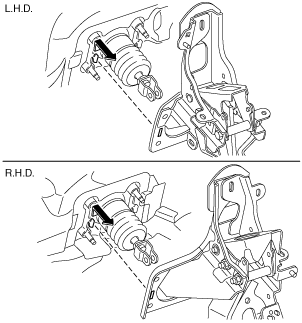
Brake Pedal Removal Note
1. For R.H.D., remove the insulator. (L5) (See MASTER CYLINDER REMOVAL/INSTALLATION [R.H.D.].)
2. Remove the brake pedal as shown in the figure.
am6zzw00001627
|
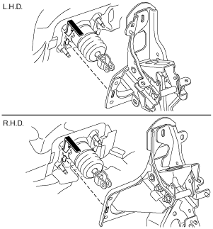
Brake Pedal Installation Note
1. Install the brake pedal as shown in the figure.
am6zzw00001628
|
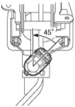
Brake Switch Installation Note
1. Inspect the brake pedal. (See BRAKE PEDAL INSPECTION.)
2. With the brake pedal fully released, insert a new brake switch into the installation hole on the brake pedal.
3. Secure the brake switch by turning it counterclockwise 45°.
am6zzw00001629
|