 |
am6zzw00002900
PRIMARY CONTROL VALVE BODY INSTALLATION [FS5A-EL]
id051721807400
On‐Vehicle Installation
am6zzw00002900
|
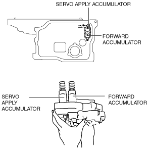
1. Install the accumulator springs and accumulators into the transaxle case.
am6zzw00002901
|
|
Spring |
Outer diameter (mm {in}) |
Free Length (mm {in}) |
No. of coils |
Wire diameter (mm {in}) |
|---|---|---|---|---|
|
Servo apply accumulator large spring
|
21.0
{0.827}
|
67.8
{2.669}
|
10.3
|
3.5
{0.138}
|
|
Servo apply accumulator small spring
|
13.0
{0.512}
|
67.8
{2.669}
|
17.1
|
2.2
{0.087}
|
|
Forward accumulator large spring
|
21.0
{0.827}
|
75.0
{2.953}
|
10.7
|
2.3
{0.091}
|
|
Forward accumulator small spring
|
15.6
{0.614}
|
49.0
{1.929}
|
7.7
|
2.4
{0.094}
|
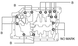
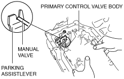
2. Install the primary control valve body component.
am6zzw00002902
|
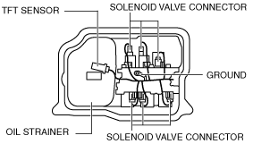
3. Install the oil strainer.
4. Match the connector colors, then connect the solenoid connectors and ground.
am6zzw00002896
|
|
Spring |
Connector color (harness side) |
|---|---|
|
Pressure control solenoid A
|
Black
|
|
Shift solenoid A
|
White
|
|
Shift solenoid B
|
Blue
|
|
Shift solenoid C
|
Green
|
|
Shift solenoid D
|
White
|
|
Shift solenoid E
|
Black
|
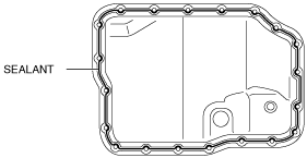
5. Apply a light coat of silicon sealant to the contact surfaces of the oil pan and transaxle case.
am6zzw00002903
|
6. Install the oil pan. (See PRIMARY CONTROL VALVE BODY INSTALLATION [FS5A-EL].)
7. Install the front crossmember. (See FRONT CROSSMEMBER REMOVAL/INSTALLATION.)
8. Add ATF. (See AUTOMATIC TRANSAXLE FLUID (ATF) REPLACEMENT [FS5A-EL].)
9. Install the aerodynamic under cover NO.2. (See AERODYNAMIC UNDER COVER NO.2 REMOVAL/INSTALLATION.)
10. Connect the negative battery cable.
11. Carry out the mechanical system test. (See MECHANICAL SYSTEM TEST [FS5A-EL].)