EPS CONTROL MODULE REMOVAL/INSTALLATION


id061300802300

Caution
•  If the EPS control module configuration is not completed, the EPS will not operate properly. If the EPS control module is replaced, always carry out the EPS control module configuration so that the EPS operates properly. (See EPS CONTROL MODULE CONFIGURATION.)
•  If the EPS control module is replaced, set the EPS system to the neutral position. If not set to the neutral position, the system may not operate correctly. (See EPS SYSTEM NEUTRAL POSITION SETTING.)
•  Do not drop the EPS control module. Replace the EPS control module if it subjected to an impact.

1.  Remove the battery and battery tray. (See BATTERY REMOVAL/INSTALLATION [L8, LF, L5].) (See BATTERY REMOVAL/INSTALLATION [MZR-CD (RF Turbo)].) (See BATTERY REMOVAL/INSTALLATION [MZR-CD 2.2].)

2.  For L.H.D., remove the vacuum tank. (MZR-CD (RF Turbo) (See MASTER CYLINDER REMOVAL/INSTALLATION [L.H.D.].)

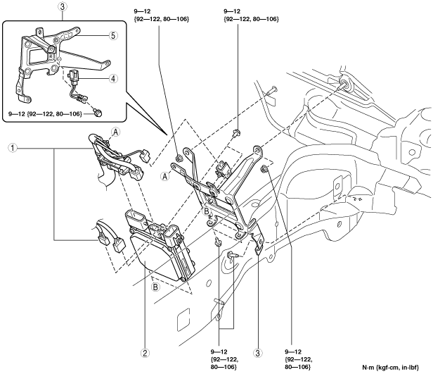
3.  Remove in the order indicated in the table.

4.  Install in the reverse order of removal.

5.  After installation, perform the configuration for the EPS control module. (See EPS CONTROL MODULE CONFIGURATION.)

6.  After installation, set the EPS system to the neutral position. (See EPS SYSTEM NEUTRAL POSITION SETTING.)

am6zzw00001977

1
EPS control module connector
2
EPS control module
3
Bracket component
4
Wiring harness
5
Bracket


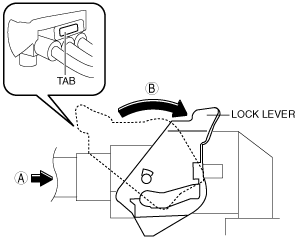
EPS control module connector Removal Note

Caution
•  If moisture or oil enters the EPS control module connector, the EPS system may not operate normally. Make sure no moisture or oil has penetrated the EPS control module connector when disconnecting the wiring harness connector from the EPS control module connector.

1.  Remove the EPS motor connector using the following procedure as shown in the figure.

am6zzw00002181

(1)  Press the tab and release the lock lever.
(2)  Rotate the lock lever in the direction of the arrow (A).
(3)  Pull the EPS motor connector in the direction of the arrow (B) and remove it.

2.  Remove the other connectors.


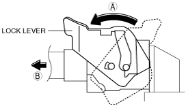
EPS control module connector Installation Note

1.  Install the EPS motor connector using the following procedure as shown in the figure.

am6zzw00002179

(1)  Push the EPS motor connector in the direction of the arrow (A) and connect it to the steering gear side EPS motor connector.
(2)  Rotate the lock lever in the direction of the arrow (B).
(3)  Verify that the EPS motor connector is locked securely.

2.  Install the other connectors.