|
1
|
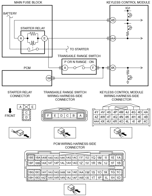
INSPECT KEYLESS CONTROL MODULE CONNECTOR CONDITION
• Switch the ignition to off.
• Disconnect the negative battery cable.
• Disconnect the keyless control module connector.
• Inspect the connector and terminals (corrosion, damage, pin disconnection).
• Is there any malfunction?
|
Yes
|
Repair or replace the connector or terminals, then go to Step 4.
|
|
3
|
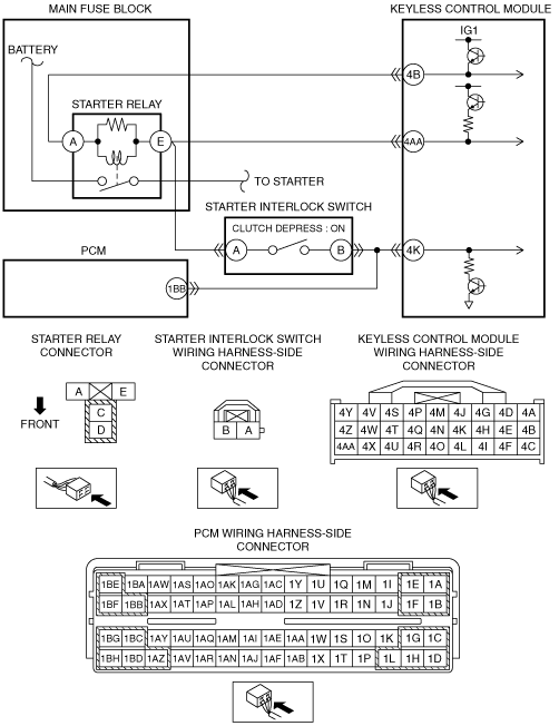
INSPECT KEYLESS CONTROL MODULE
• Reconnect the disconnected connectors.
• Reconnect the negative battery cable.
• Bring the valid key into the vehicle.
• Measure the voltage between the following terminals and body ground with the clutch depressed:
-
― Keyless control module terminal 4B (wiring harness-side)
― Keyless control module terminal 4AA (wiring harness-side)
• Is the voltage more than 4 V?
|
Yes
|
Go to the next step.
|
|
4
|
VERIFY TROUBLESHOOTING COMPLETED
• Make sure to reconnect the disconnected connectors.
• Reconnect the negative battery cable.
• Clear the DTC from keyless control module memory using the M-MDS.
• Perform the advanced keyless entry and push button start system DTC inspection using the M-MDS.
• Is the same DTC present?
|
Yes
|
Repeat the inspection from Step 1.
If the malfunction recurs, replace the keyless control module, then go to the next step.
|