 |
am6zzw00002150
DTC B1172:11 [BCM]
id0902f5415100
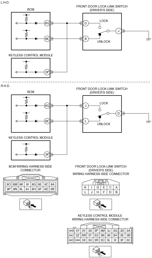
Vehicles With Advanced Keyless Entry And Push Button Start System
Malfunction Location
Detection Condition
Possible Causes
System Wiring Diagram
am6zzw00002150
|
Diagnostic Procedure
|
Step |
Inspection |
Action |
|
|---|---|---|---|
|
1
|
PERFORM DTC INSPECTION
• Clear DTCs using the M-MDS.
(See CLEARING DTC [BCM].)
• Perform the BCM DTC inspection using the M-MDS with the front door lock-link switch (driver's side) unlocked.
(See DTC INSPECTION [BCM].)
• Is DTC B1172:11 displayed?
|
Yes
|
Go to the next step.
|
|
No
|
DTC troubleshooting completed.
|
||
|
2
|
INSPECT FRONT DOOR LOCK-LINK SWITCH (DRIVER’S SIDE) CONNECTOR CONDITION
• Switch the ignition to off.
• Disconnect the negative battery cable.
• Disconnect the front door lock-link switch (driver’s side) connector.
• Inspect the connector and terminals (corrosion, damage, pin disconnection).
• Is the connector normal?
|
Yes
|
Go to the next step.
|
|
No
|
Repair/replace the connector or terminal.
After repair procedure, go to Step 8.
|
||
|
3
|
INSPECT FRONT DOOR LOCK-LINK SWITCH (DRIVER’S SIDE)
• Inspect the front door lock-link switch (driver’s side).
• Is the front door lock-link switch (driver’s side) normal?
|
Yes
|
Go to the next step.
|
|
No
|
Replace the front door lock-link switch (driver’s side).
After replacement, go to Step 8.
|
||
|
4
|
INSPECT KEYLESS CONTROL MODULE CONNECTOR CONDITION
• Disconnect the keyless control module connector.
• Inspect the connector and terminals (corrosion, damage, pin disconnection).
• Is the connector normal?
|
Yes
|
Go to the next step.
|
|
No
|
Repair/replace the connector or terminal.
After repair procedure, go to Step 8.
|
||
|
5
|
INSPECT BCM CONNECTOR CONDITION
• Disconnect the BCM connector.
• Inspect the connector and terminals (corrosion, damage, pin disconnection).
• Is the connector normal?
|
Yes
|
Go to the next step.
|
|
No
|
Repair/replace the connector or terminal.
After repair procedure, go to Step 8.
|
||
|
6
|
INSPECT FRONT DOOR LOCK-LINK SWITCH (DRIVER’S SIDE) CIRCUIT FOR SHORT CIRCUIT TO GROUND
L.H.D.
• Inspect for continuity between front door lock-link switch (driver’s side) connector terminal D and body ground.
• Is there continuity?
R.H.D.
• Inspect for continuity between front door lock-link switch (driver’s side) connector terminal J and body ground.
• Is there continuity?
|
Yes
|
Repair/replace the wiring harness.
After repair procedure, go to Step 8.
|
|
No
|
Go to the next step.
|
||
|
7
|
INSPECT KEYLESS CONTROL MODULE
• Reconnect the keyless control module connector.
• Reconnect the negative battery cable.
• Measure the voltage at the keyless control module connector terminal 3P.
• Is the voltage normal?
|
Yes
|
Go to the next step.
|
|
No
|
Replace the keyless control module.
(See KEYLESS CONTROL MODULE REMOVAL/INSTALLATION [ADVANCED KEYLESS ENTRY AND PUSH BUTTON START SYSTEM].)
After replacement, go to the next step.
|
||
|
8
|
VERIFY DTC
• Reconnect the disconnected connectors and the negative battery cable.
• Clear DTCs using the M-MDS.
(See CLEARING DTC [BCM].)
• Perform the BCM DTC inspection using the M-MDS with the front door lock-link switch (driver's side) unlocked.
(See DTC INSPECTION [BCM].)
• Is the same DTC present?
|
Yes
|
Repeat the inspection from Step 1.
If the malfunction recurs, replace the BCM.
Go to the next step.
|
|
No
|
Go to the next step.
|
||
|
9
|
VERIFY THAT NO OTHER DTCs ARE PRESENT
• Are there other DTCs output?
|
Yes
|
Perform the corresponding DTC inspection.
|
|
No
|
DTC troubleshooting completed.
|
||
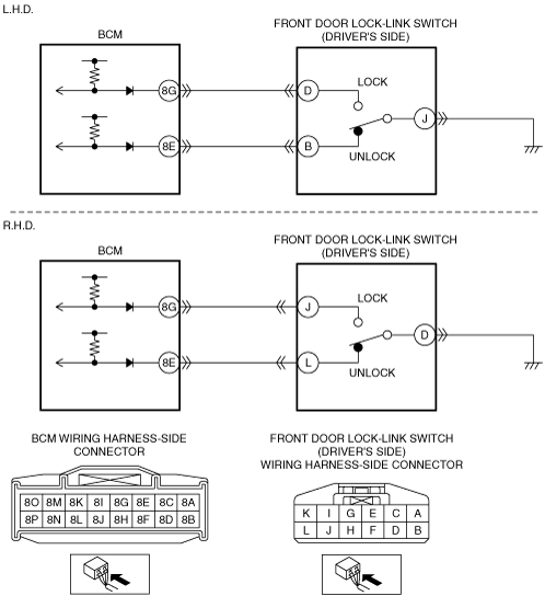
Vehicles With Keyless Entry System
Malfunction Location
Detection Condition
Possible Causes
System Wiring Diagram
am6zzw00002151
|
Diagnostic Procedure
|
Step |
Inspection |
Action |
|
|---|---|---|---|
|
1
|
PERFORM DTC INSPECTION
• Clear DTCs using the M-MDS.
(See CLEARING DTC [BCM].)
• Perform the BCM DTC inspection using the M-MDS with the front door lock-link switch (driver's side) unlocked.
(See DTC INSPECTION [BCM].)
• Is DTC B1172:11 displayed?
|
Yes
|
Go to the next step.
|
|
No
|
DTC troubleshooting completed.
|
||
|
2
|
INSPECT FRONT DOOR LOCK-LINK SWITCH (DRIVER’S SIDE) CONNECTOR CONDITION
• Switch the ignition to off.
• Disconnect the negative battery cable.
• Disconnect the front door lock-link switch (driver’s side) connector.
• Inspect the connector and terminals (corrosion, damage, pin disconnection).
• Is the connector normal?
|
Yes
|
Go to the next step.
|
|
No
|
Repair/replace the connector or terminal.
After repair procedure, go to Step 6.
|
||
|
3
|
INSPECT FRONT DOOR LOCK-LINK SWITCH (DRIVER’S SIDE)
• Inspect the front door lock-link switch (driver’s side).
• Is the front door lock-link switch (driver’s side) normal?
|
Yes
|
Go to the next step.
|
|
No
|
Replace the front door lock-link switch (driver’s side).
After replacement, go to Step 6.
|
||
|
4
|
INSPECT BCM CONNECTOR CONDITION
• Disconnect the BCM connector.
• Inspect the connector and terminals (corrosion, damage, pin disconnection).
• Is the connector normal?
|
Yes
|
Go to the next step.
|
|
No
|
Repair/replace the connector or terminal.
After repair procedure, go to Step 6.
|
||
|
5
|
INSPECT FRONT DOOR LOCK-LINK SWITCH (DRIVER’S SIDE) CIRCUIT FOR SHORT CIRCUIT TO GROUND
L.H.D.
• Inspect for continuity between front door lock-link switch (driver’s side) connector terminal D and body ground.
• Is there continuity?
R.H.D.
• Inspect for continuity between front door lock-link switch (driver’s side) connector terminal J and body ground.
• Is there continuity?
|
Yes
|
Repair/replace the wiring harness.
After repair procedure, go to the next step.
|
|
No
|
Go to the next step.
|
||
|
6
|
VERIFY DTC
• Reconnect the disconnected connectors and the negative battery cable.
• Clear DTCs using the M-MDS.
(See CLEARING DTC [BCM].)
• Perform the BCM DTC inspection using the M-MDS with the front door lock-link switch (driver's side) unlocked.
(See DTC INSPECTION [BCM].)
• Is the same DTC present?
|
Yes
|
Repeat the inspection from Step 1.
If the malfunction recurs, replace the BCM.
Go to the next step.
|
|
No
|
Go to the next step.
|
||
|
7
|
VERIFY THAT NO OTHER DTCs ARE PRESENT
• Are there other DTCs output?
|
Yes
|
Perform the corresponding DTC inspection.
|
|
No
|
DTC troubleshooting completed.
|
||