|
1
|
• Verify that the advanced keyless entry and push button start system is operating.
• Is the advanced keyless entry and push button start system operating normally?
|
Yes
|
Go to the next step.
|
|
No
|
Go to applicable malfunction diagnostic procedure.
|
|
2
|
• Does the system switch to ACC and IG-ON (IG1)?
|
Yes
|
Go to the next step.
|
|
No
|
Go to symptom troubleshooting procedure “No.3 Push button start does not operate”.
|
|
3
|
• Verify the keyless control module DTCs using the M-MDS.
• Can DTCs be verified?
|
Yes
|
Go to the applicable DTC inspection.
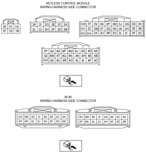
If the FAIL is displayed on the M-MDS, inspect for open circuit between connector terminal 2G, 2I on the keyless control module vehicle wiring harness and DLC-2.
|
|
No
|
Go to the next step.
|
|
4
|
• Switch the ignition to off.
• Disconnect the keyless control system connector.
• Verify the continuity between connector terminal 1F on the keyless control module vehicle wiring harness side and ground.
• Can continuity be verified?
|
Yes
|
Go to the next step.
|
|
No
|
After repairing or replacing for an open circuit in the wiring harness, go to Step 18.
|
|
5
|
• Leave the keyless control module connector disconnected.
• Switch the ignition to off.
• Disconnect the DSC CM connector.
• Verify continuity at the following harness-side connector terminals:
-
― Between keyless control module terminal 4S and BCM terminal 6K
― Between DSC CM terminal AF and BCM terminal 1E
• Can continuity be verified?
|
Yes
|
Go to the next step.
|
|
No
|
After repairing or replacing for an open circuit in the wiring harness, go to Step 18.
|
|
6
|
• Does the engine stop normally?
|
Yes
|
Go to the next step.
|
|
No
|
Go to Step 9.
|
|
7
|
• Lock the doors using the advanced keyless entry mechanism.
• Does the steering lock mechanism lock?
|
Yes
|
Go to the next step.
|
|
No
|
Go to Step 12.
|
|
8
|
• Switch the ignition to off.
• Change the door condition (Open→Close, Close→Open)
• Does the steering lock mechanism lock?
|
Yes
|
After repairing or replacing for intermittent connection malfunctions of the following part connectors and malfunction areas, go to Step 18.
• Keyless control module
• BCM
• Electronic steering lock unit
|
|
No
|
Go to Step 17.
|
|
9
|
• Monitor the instrument cluster PID SPDMTR using the M-MDS data monitor function.
• Is the monitor value when the vehicle is stopped 0 km/h?
|
Yes
|
Go to Step 11.
|
|
No
|
Go to the next step.
|
|
10
|
• Monitor the following PIDs concerning the ABS (ABS equipped vehicles) and DSC (DSC equipped vehicle) CM using the M-MDS data monitor function.
-
― LF_WSPD
― LR_WSPD
― RF_WSPD
― RR_WSPD
• Does the monitor value agree with the vehicle driving conditions?
|
Yes
|
Go to the instrument cluster symptom troubleshooting “Speedometer indication malfunction”.
|
|
No
|
Inspect the ABS wheel-speed sensor.
After inspection and repair, go to Step 18.
|
|
11
|
• Verify the keyless control module PID LOCK_SW_D (door lock signal) using the M-MDS data monitor function.
• Is the monitor value linked to the door lock condition?
|
Yes
|
Replace the steering lock unit, then go to Step 18.
|
|
No
|
Go to the next step.
|
|
12
|
• Switch the ignition to off.
• Disconnect the keyless control module, BCM, and door lock link switch connectors.
• Verify the continuity between the following connector terminals on the vehicle wiring harness side:
-
― Between keyless control module terminal 3P and door lock link switch terminal D.
― Between BCM terminal 8G and door lock link switch terminal D
• Is there continuity?
|
Yes
|
Go to the next step.
|
|
No
|
After repairing or replacing for an open circuit in the wiring harness, go to Step 18.
|
|
13
|
• Leave the keyless control module, BCM, door lock link switch connectors disconnected.
• Verify the continuity between connector terminal 3P of the keyless control module on the vehicle wiring harness side and ground.
• Is there continuity?
|
Yes
|
• After repairing or replacing for an open circuit in the wiring harness, go to Step 18.
• Between keyless control module terminal 3P and door lock link switch terminal D.
• Between BCM terminal 8G and door lock link switch terminal D
|
|
No
|
Go to the next step.
|
|
14
|
• Leave the keyless control module, BCM, door lock link switch connectors disconnected.
• Measure the voltage of connector terminal 3P on the keyless control module vehicle wiring harness side.
• Is the voltage 1.0 V or more?
|
Yes
|
• After repairing or replacing for an open circuit in the wiring harness, go to Step 18.
• Between keyless control module terminal 3P and door lock link switch terminal D.
• Between BCM terminal 8G and door lock link switch terminal D
|
|
No
|
Go to the next step.
|
|
15
|
• Leave the door lock link switch connector disconnected.
• Verify the continuity between connector terminal J on the door lock link switch vehicle wiring harness side and ground.
• Is there continuity?
|
Yes
|
Go to the next step.
|
|
No
|
• Inspect the following and repair or replace the malfunctioning location.
-
― Wiring harness between connector terminal J of the door lock link switch vehicle wiring harness side (open circuit).
― Ground point (looseness, bad contact)
• After repair procedure, go to Step 18.
|
|
16
|
• Inspect the door lock-link switch.
• Is the door lock-link switch normal?
|
Yes
|
Go to the next step.
|
|
No
|
Replace the door lock-link switch.
After replacement, go to Step 18.
|
|
17
|
• Leave the keyless control module and BCM connectors disconnected.
• Measure the voltage of connector terminal 2F on the keyless control module vehicle wiring harness side.
• Is the voltage 1.0 V or more?
|
Yes
|
After repairing or replacing for a short to the power supply wiring harness, go to Step 16.
|
|
No
|
Replace the keyless control module.
|
|
18
|
• Is the electronic steering lock operating normally?
|
Yes
|
Troubleshooting completed.
Explain the contents of the servicing to the customer.
|
|
No
|
If the malfunction has not been resolved, repeat the inspection from Step 1.
|