|
1
|
• Verify the keyless control module DTCs using the M-MDS.
• Can DTCs be verified?
|
Yes
|
Go to the applicable DTC inspection.
|
|
No
|
Go to the next step.
|
|
2
|
• Perform engine stop operation.
• Does the engine stop normally?
|
Yes
|
Go to Step 8.
|
|
No
|
Go to the next step.
|
|
3
|
• Connect the M-MDS to the DLC-2 connector.
• Monitor the keyless control module PID PUSH_ST1, and PUSH_ST2.
• Operate the push button start.
• Does the PID display change according to the push button start status?
-
― While push button start is pressed: ON
― While push button start is not pressed: OFF
|
Yes
|
Go to Step 6.
|
|
No
|
Go to the next step.
|
|
4
|
• Switch the ignition to off.
• Disconnect the push button start connector.
• Verify the continuity between connector terminal I on the push start switch vehicle wiring harness side and ground.
• Can continuity be verified?
|
Yes
|
Go to the next step.
|
|
No
|
• Inspect the following and repair or replace the malfunctioning location.
-
― Wiring harness between push button start and ground (open circuit).
― Ground point (looseness, bad contact)
• If there is no malfunction, replace the push button start.
After repair procedure, go to Step 13.
|
|
5
|
• Switch the ignition to off.
• Leave the push button start connector disconnected.
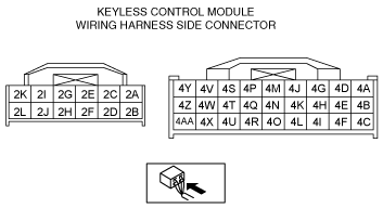
• Disconnect the keyless control module connector (12-pin).
• Verify the continuity between the following connector terminals on the push button start vehicle wiring harness side and ground.
-
― Terminal A
― Terminal B
• Can continuity be verified?
|
Yes
|
• Repair for a short to ground in the wiring harness between the push button start and the keyless control module.
• After repair procedure, go to Step 13.
|
|
No
|
• Replace the push button start.
• After replacement, go to Step 13.
|
|
6
|
• Monitor the instrument cluster PID SPDMTR using the M-MDS data monitor function.
• Is the monitor value when the vehicle is stopped 0 km/h?
|
Yes
|
Go to Step 8.
|
|
No
|
Go to the next step.
|
|
7
|
• Monitor the following PIDs concerning the ABS (ABS equipped vehicles) and DSC (DSC equipped vehicle) CM using the M-MDS data monitor function.
-
― LF_WSPD
― LR_WSPD
― RF_WSPD
― RR_WSPD
• Does the monitor value agree with the vehicle driving conditions?
|
Yes
|
Go to the instrument cluster symptom troubleshooting ”Speedometer indication malfunction”.
|
|
No
|
Inspect the ABS wheel-speed sensor.
After inspection and repair, go to Step 13.
|
|
8
|
• Disconnect the keyless control module connector.
• Connect battery positive voltage to the following connector terminals on the keyless control module vehicle wiring harness side.
-
― Terminal 4F (ACC)
― Terminal 4E (IG1)
― Terminal 4H (IG2)
• Measure the voltage of the following connector terminals on the keyless control module vehicle wiring harness side.
-
― Terminal 2A (ACC)
― Terminal 2C (IG1)
― Terminal 4X (IG2)
• Is the voltage B+?
|
Yes
|
Replace the keyless control module.
After replacement, go to Step 13.
|
|
No
|
Go to the next step.
|
|
9
|
• Leave the keyless control module connector disconnected.
• Disconnect the relay block connector.
• Verify the continuity between the following connector terminals on the vehicle wiring harness side:
-
― Between keyless control module terminal 4F and relay block terminal E (8-pin) (ACC relay primary power supply).
― Between keyless control module terminal 4E and relay block terminal G (8-pin) (IG1relay primary power supply).
― Between keyless control module terminal 4H and relay block terminal A (8-pin) (IG2 relay primary power supply).
• Can continuity be verified?
|
Yes
|
Go to the next step.
|
|
No
|
After repairing for an open circuit in the wiring harness, go to Step 13.
|
|
10
|
• Leave the relay block connector disconnected.
• Verify the continuity between connector terminal 2C on the relay block vehicle wiring harness side and ground.
• Can continuity be verified?
|
Yes
|
Go to the next step.
|
|
No
|
Repair the open circuit in the wiring harness.
Inspect and repair the ground point.
After repair procedure, go to Step 13.
|
|
12
|
• Leave the relay block connector disconnected.
• Measure the voltage of connector terminal 1A (6-pin) and terminal 1E (6-pin) on the relay block vehicle wiring harness side.
• Is the voltage B+?
|
Yes
|
Go to the next step.
|
|
No
|
After repairing for an open circuit in the wiring harness, go to Step 13.
|
|
13
|
• Inspect the relay block.
• Is the relay block normal?
|
Yes
|
• Replace the keyless control module.
• After replacement, go to the next step.
|
|
No
|
Replace the relay block, then go to the next step.
|
|
14
|
• Is the electronic steering lock operating normally?
|
Yes
|
Troubleshooting completed.
Explain the contents of the servicing to the customer.
|
|
No
|
If the malfunction has not been resolved, repeat the inspection from Step 1.
|