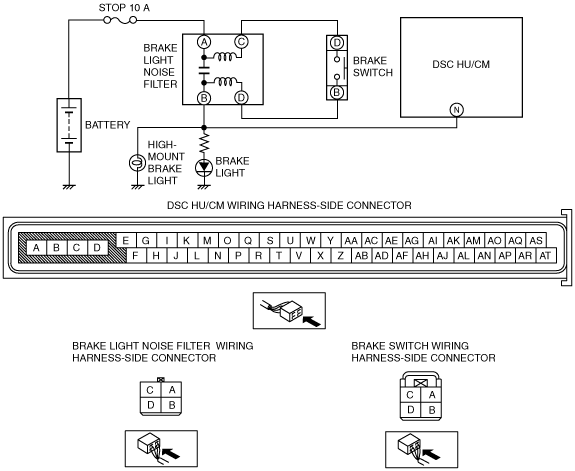
DTC B1484, C1954 [DYNAMIC STABILITY CONTROL (DSC)]


id0402b2800500

DTC
B1484, C1954
Brake switch system
DETECTION CONDITION
•  B1484
―  Open circuit is detected in wiring harness between DSC HU/CM—brake switch (Voltage at the DSC HU/CM terminal N is more than 40% and less than 67% of the voltage at the DSC HU/CM terminal J for 0.5 s continuously.).
•  C1954
―  Brake switch ON signal is input even though signal from brake fluid pressure sensor is lower than specified value (While vehicle is driven at a speed of 10.8 km/h or more, brake switch is continuously ON for 60 s with accelerator pedal ON and brake fluid pressure 500 kPa or lower, not operated).
―  Brake fluid pressure sensor signal value is continuously more than 1,000 kPa for 1 s with brake switch signal OFF.
FAIL-SAFE
•  Inhibits ABS, TCS, and DSC controls, and illuminates ABS warning light, DSC indicator light and brake system warning light (vehicle without the malfunction warning light)* / malfunction warning light (vehicle equipped with the malfunction warning light)*.
(If error is detected during ABS/TCS control, inhibits ABS/TCS control after finishing the control and illuminates ABS warning light.)
POSSIBLE CAUSE
•  STOP 10 A fuse malfunction
•  Brake switch malfunction
•  Brake light noise filter malfunction
•  Open circuit or short to ground in the wiring harness between the DSC HU/CM terminal N and the brake switch terminal D
•  Brake light malfunction
•  High-mount brake light malfunction
•  Brake fluid pressure sensor malfunction in DSC HU/CM

*  :Applied VIN (assumed) FE10**301152—

Diagnostic procedure

STEP

INSPECTION

ACTION

1
INSPECT BRAKE PEDAL POSITION SIGNAL INPUT TO DSC HU/CM USING M-MDS
•  Connect the M-MDS to the DLC-2.
•  Select the “BOO_ABS” PID and verify that the display is switched as follows according to the brake pedal condition:
―  Brake pedal depressed: On
―  Brake pedal released: Off
•  Does the “BOO_ABS” PID change normally?
Yes
Go to Step 6.
No
Go to the next step.
2
INSPECT STOP LIGHT FUSE CONDITION
•  Turn the ignition switch off.
•  Inspect the STOP 10 A fuse.
•  Is the STOP 10 A fuse normal?
Yes
Go to the next step.
No
Replace the fuse, then go to Step 7.
3
INSPECT BRAKE SWITCH
•  Inspect the brake switch.
•  Is the brake switch normal?
Yes
Go to the next step.
No
Replace the brake switch, then go to Step 7.
4
INSPECT BRAKE LIGHT NOISE FILTER
•  Inspect the brake light noise filter.
•  Is the brake light noise filter normal?
Yes
Go to the next step.
No
Replace the wiring harness (including the brake light noise filter), then go to Step 7.
Note
•  The brake light noise filter is integrated with the wiring harness and cannot be replaced individually. Therefore, if there is a malfunction of the brake light noise filter, replace the wiring harness.
5
INSPECT FOR OPEN CIRCUIT IN WIRING HARNESS BETWEEN DSC HU/CM AND STOP LIGHT FUSE
•  Disconnect the DSC HU/CM, brake switch, and brake light noise filter connectors.
•  Inspect the vehicle wiring harness-side connectors for continuity between the following terminals:
―  STOP 10 A fuse—brake light noise filter terminal A
―  Brake light noise filter terminal C—brake switch terminal D
―  Brake switch terminal D—brake light noise filter terminal B
―  Brake light noise filter terminal B—DSC HU/CM terminal N
•  Is there continuity?
Yes
Go to the next step.
No
Repair or replace the wiring harness for open circuit between brake switch, brake light noise filter and DSC HU/CM, then go to Step 7.
6
INSPECT BRAKE FLUID PRESSURE SENSOR
•  Inspect the brake fluid pressure sensor.
•  Is the brake fluid pressure sensor normal?
Yes
Go to the next step.
No
Replace the DSC HU/CM, then go to the next step.
7
VERIFY DTC TROUBLESHOOTING COMPLETED
•  Make sure to reconnect all disconnected connectors.
•  Clear the DTC from the memory.
•  Start the engine and drive the vehicle at 20 km/h {13 mph} or more for 60 s or more.
•  Are the same DTCs present?
Yes
Repeat the inspection from Step 1.Replace the DSC HU/CM, then go to the next step.
If the malfunction recurs, replace the DSC HU/CM, then go to the next step.
No
Go to the next step.
8
VERIFY AFTER REPAIR PROCEDURE
•  Are any other DTCs present?
Yes
Go to the applicable DTC inspection.
No
DTC troubleshooting completed.