|
1
|
INSPECT DRIVER-SIDE AIR BAG MODULE CONNECTOR
-
Warning
-
• Handling the component parts improperly can accidentally operate (deploy) the air bag module, which may seriously injure you. Read the service warnings/cautions and the workshop manual before handling the air bag system components.
• Turn the ignition switch to the LOCK position.
• Disconnect the negative battery cable and wait for 1min or more.
• Remove the driver-side air bag module.
• Inspect the driver-side air bag module connector. (Corrosion, damage, and disconnected pins)
• Is there any malfunction of the driver-side air bag module connector?
|
Yes
|
Replace the driver-side air bag wiring harness.
|
|
No
|
Go to the next step.
|
|
2
|
INSPECT DRIVER-SIDE AIR BAG MODULE (INFLATOR NO.1)
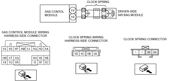
• Connect the leads of the SST (Fuel and thermometer checker) or apply 2-ohm resistance to clock spring connector terminals A and B.
• Set the resistance of the SST (Fuel and thermometer checker) to the 2-ohm position.
• Connect the negative battery cable.
• Perform the DTC inspection for the SAS control module using the M-MDS.
• Are DTCs B1913, B1916, B1932 and/or B1934 displayed.
|
Yes
|
Go to the next step.
|
|
No
|
Replace the driver-side air bag module.
|
|
3
|
INSPECT CLOCK SPRING
• Turn the ignition switch to the LOCK position.
• Disconnect the negative battery cable and wait for 1 min or more.
• Remove the steering wheel.
• Remove the column cover.
• Remove the clock spring.
• Inspect for continuity between clock spring connector terminals 1C—3B and 1D—3A.
• Is there continuity?
|
Yes
|
Go to the next step.
|
|
No
|
Replace the clock spring.
|
|
4
|
INSPECT WIRING HARNESS BETWEEN SAS CONTROL MODULE AND CLOCK SPRING
• Disconnect the SAS control module connector.
• Inspect the wiring harness between SAS control module connector terminal 1V and clock spring connector terminal 1C, and SAS control module connector terminal 1S and clock spring connector terminal 1D for the following:
-
― Short to ground
― Open circuit
-
Note
-
• Inspect for continuity while shaking the wiring harness between the SAS control module and clock spring.
• Is the wiring harness normal?
|
Yes
|
Go to the next step.
|
|
No
|
Replace the air bag wiring harness.
|
|
5
|
INSPECT WIRING HARNESS BETWEEN SAS CONTROL MODULE AND CLOCK SPRING
• Connect the negative battery cable.
• Turn the ignition switch to the ON position.
• Measure the voltage of SAS control module connector terminals 1V and 1S.
-
Note
-
• Measure the voltage while shaking the wiring harness between the SAS control module and driver-side air bag module.
• Is the voltage measured?
|
Yes
|
Replace the air bag wiring harness.
|
|
No
|
Go to the next step.
|
|
6
|
INSPECT DTCs
• Disconnect the negative battery cable and wait for 1 min or more.
• Connect the disconnected connector.
• Connect the negative battery cable.
• Clear DTCs using the M-MDS.
• Verify DTCs using the M-MDS.
• Is DTC B1913, B1916, B1932 and/or B1934 displayed again?
• Are there other DTCs output?
|
Yes
|
Replace the SAS control module.
|
|
No
|
DTC troubleshooting completed.
|