STEP
INSPECTION
ACTION
1
• Start the engine.
• Release the parking brake.
• Does the brake system warning light turn off?
Yes
Troubleshooting completed.
No
Go to the next step.
2
• Are there a number of warning lights illuminated?
Yes
Go to Step 6.
No
Go to the next step.
3
• Does the brake fluid need replenishment?
Yes
Add brake fluid.
No
Vehicles with brake override system, without malfunction warning light:
• Go to the next step.
Others:
• Go to Step 5.
4
• Reactive the DTC of PCM using M-MDS.
• Is the DTC P0571 or P0703 detected?
Yes
Go to applicable DTC troubleshooting procedure.
(See DTC P0571 [13B-MSP].)
(See DTC P0703 [13B-MSP].)
No
Go to the next step.
5
• Disconnect the negative battery cable.
• Measure the resistance between the DLC-2 terminals F and E.
• Is the resistance below 60 ohms?
Yes
Go to the next step.
No
Go to Step 8.
6
• Disconnect the negative battery cable.
• Inspect the DLC-2 terminals F and E for short to power supply or GND.
• Is there any malfunction?
Yes
Inspect the wiring harness and CAN system-related module.
Repair or replace the malfunctioning part.
No
Replace the instrument cluster.
7
• Connect the M-MDS to DLC-2.
• Retrieve the on-demand and continuous memory DTC from DSC HU/CM.
• Is there any DTC displayed?
Yes
Perform the appropriate DTC troubleshooting procedure.
No
Go to the next step.
8
• Turn the ignition switch to LOCK position.
• Inspect the instrument cluster connector terminals for poor connection (such as damaged/pulled-out pins, and corrosion).
• Are the terminals normal?
Yes
Go to the next step.
No
Repair or replace the terminal.
9
• Disconnect the negative battery cable.
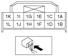
• Measure the resistance between the instrument cluster connector terminals 1J and 1L.
• Is the resistance 114—126 ohms?
Yes
Inspect the wiring harness and CAN system-related module.
Repair or replace the malfunctioning part.
No
Replace the instrument cluster.