|
1
|
VERIFY RELATED SERVICE INFORMATION AVAILBAILITY
• Verify related Service information availability.
• Is any related Service information available?
|
Yes
|
Perform repair or diagnosis according to th available Service information.
• If the vehicle is not repaired, go to the next step.
|
|
No
|
Go to the next step.
|
|
2
|
VERIFY RELATED PENDING CODE OR STORED DTC
• Turn the ignition switch off, then to the ON position (engine off).
• Verify the related PENDING CODE or stored DTCs.
• Are other DTCs present?
|
Yes
|
Go to the appropriate DTC inspection.
|
|
No
|
Go to the next step.
|
|
3
|
INSPECT BRAKE SWITCH CONNECTOR FOR POOR CONNECTION
• Turn the ignition switch off.
• Disconnect the brake switch connector.
• Inspect for poor connection (such as damaged/pulled-out pins, corrosion).
• Is there any malfunction?
|
Yes
|
Repair or replace the terminal, then go to Step 11.
|
|
No
|
Go to the next step.
|
|
4
|
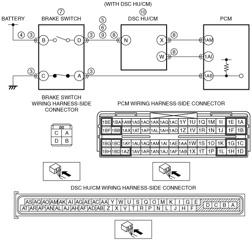
INSPECT BRAKE SWITCH POWER CIRCUIT FOR OPEN CIRCUIT OR SHORT TO GROUND
• Turn the ignition switch to the ON position (engine off).
• Measure the voltage between brake switch terminal B (wiring harness-side) and body ground.
• Is the voltage B+?
|
Yes
|
Go to the next step.
|
|
No
|
Repair or replace the wiring harness for a possible open circuit or short to ground, then go to Step 11.
|
|
5
|
INSPECT BRAKE SWITCH SIGNAL CIRCUIT FOR SHORT TO GROUND
• Turn the ignition switch off.
• Inspect for continuity between brake switch terminal D (wiring harness-side) and body ground.
• Is there continuity?
|
Yes
|
Repair or replace the wiring harness for a possible short to ground, then go to Step 11.
|
|
No
|
Go to the next step.
|
|
6
|
INSPECT BRAKE SWITCH SIGNAL CIRCUIT FOR SHORT TO POWER SUPPLY
• Turn the ignition switch to the ON position (engine off).
• Measure the voltage between brake switch terminal D (wiring harness-side) and body ground.
• Is the voltage B+?
|
Yes
|
Repair or replace the wiring harness for a possible short to power supply, then go to Step 11.
|
|
No
|
Go to the next step.
|
|
7
|
INSPECT BRAKE SWITCH
• Inspect the brake switch.
• Is there any malfunction?
|
Yes
|
Replace the brake switch, then go to Step 11.
|
|
No
|
Go to the next step.
|
|
8
|
INSPECT DSC HU/CM CONNECTOR FOR POOR CONNECTION
• Turn the ignition switch off.
• Disconnect the DSC HU/CM connector.
• Inspect for poor connection (such as damaged/pulled-out pins, corrosion).
• Is there any malfunction?
|
Yes
|
Repair or replace the terminal, then go to Step 11.
|
|
No
|
Go to the next step.
|
|
9
|
INSPECT BRAKE SWITCH SIGNAL CIRCUIT FOR OPEN CIRCUIT
• Turn the ignition switch off.
• Inspect for continuity between the following circuit:
-
― Brake switch terminal D (wiring harness-side) and DSC HU/CM terminal N (wiring harness-side) (with DSC HU/CM)
• Is there continuity?
|
Yes
|
Go to the next step.
|
|
No
|
Repair or replace the wiring harness for a possible open circuit, then go to Step 11.
|
|
10
|
INSPECT DSC HU/CM
• Is there any malfunction?
|
Yes
|
Replace the DSC HU/CM, then go to the next step.
|
|
No
|
Go to the next step.
|
|
11
|
VERIFY TROUBLESHOOTING OF DTC P0571 COMPLETED
• Make sure to reconnect all disconnected connectors.
• Clear the DTC from the PCM memory using the M-MDS.
• Start the engine.
• Operate the brake pedal.
• Is the same DTC present?
|
Yes
|
Replace the PCM, then go to the next step.
|
|
No
|
Go to the next step.
|
|
12
|
VERIFY AFTER REPAIR PROCEDURE
• Perform the “AFTER REPAIR PROCEDURE”.
• Are any DTCs present?
|
Yes
|
Go to the applicable DTC inspection.
|
|
No
|
DTC troubleshooting completed.
|