FUEL INJECTOR REMOVAL/INSTALLATION
id011400800600
1. Follow the before repair procedure and perform fuel line safety procedure. (See BEFORE REPAIR PROCEDURE.)
2. Disconnect the negative battery cable. (See BATTERY REMOVAL/INSTALLATION.)
3. Remove the extension manifold (upper). (See INTAKE-AIR SYSTEM REMOVAL/INSTALLATION.)
4. Remove the extension manifold (lower). (See INTAKE-AIR SYSTEM REMOVAL/INSTALLATION.)
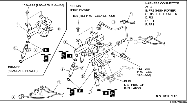
5. Remove in the order indicated in the table.
|
1
|
Harness connector
|
|
2
|
Quick release connector
|
|
3
|
Fuel injector (intake manifold side)
|
|
4
|
Fuel distributor (intake manifold side)
|
|
5
|
Fuel distributor (housing side)
|
|
6
|
Fuel injector (housing side)
|
6. Install in the reverse order of removal.
7. Inspect all parts by performing the "AFTER REPAIR PROCEDURE". (See AFTER REPAIR PROCEDURE.)
Fuel Injector (Intake Manifold Side) Removal Note
1. Lift up the fuel distributor (intake manifold side) slightly and remove the fuel injector (intake manifold side).
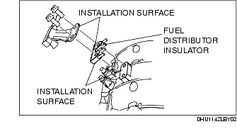
Fuel Distributor (Housing Side) Installation Note
-
Caution
-
• If the fuel distributor and fuel distributor insulator are installed with foreign material adhering to the installation surfaces, cracking or splitting could occur, causing a malfunction such as whistling noise or abnormal acceleration. Always verify that there is no foreign material adhering to the installation surfaces and clean these areas if necessary before installing the fuel distributor and fuel distributor insulator.
Harness Connector Installation Note
-
Caution
-
• Improper connection of the wiring harness connectors for primary injectors 1 and 2 may occur because the connectors on the front and rear rotor sides have the same shape. When connecting the wiring harnesses and injectors, verify the colored identification tape affixed on the wiring harness side and the injector positions, and then connect the wiring harness connectors to the proper injectors. If the colored tape has peeled off or was never affixed, verify injector connection according to the colors of the wires.
1. Verify the colors of the identification tape on the wiring harness connectors and the injector connections according to the following table.
-
• If there is no colored tape, identify injector connection according to the colors of the wires and connect the wiring harness connectors.
Identification tape color
-: Not applicable
|
Harness Connector
|
Identification tape color
|
|
FP1
|
White
|
|
RP1
|
Orange
|
|
FP2
|
Yellow
|
|
RP2
|
Green
|
|
FS
|
-
|
|
RS
|
-
|