DTC U0214 [ADVANCED KEYLESS SYSTEM]
id0902e2351200
DTC U0214
Keyless receiver.
DETECTION CONDITION
• When the keyless receiver power supply voltage is
less than 7.5 V
.
POSSIBLE CAUSE
• Keyless receiver malfunction
• Open or short circuit in wiring harness between keyless control module and keyless receiver
• Keyless control module malfunction
Diagnostic procedure
STEP
INSPECTION
ACTION
1
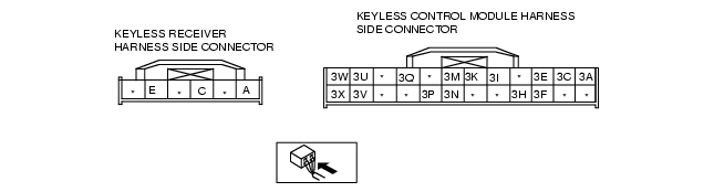
INSPECT WIRING HARNESS BETWEEN KEYLESS RECEIVER AND GROUND
• Disconnect keyless receiver connector.
• Is there continuity between keyless receiver terminal E and ground?
Yes
Go to next step.
No
• Repair the wiring harness between the keyless receiver and ground.
• Go to next step.
2
INSPECT COMMUNICATION CIRCUIT FOR CONTINUITY
• Disconnect keyless control module connector and keyless receiver connector.
• Inspect the continuity between the following connector terminals.
- keyless control module: 3A-keyless receiver: A
- keyless control module: 3C-keyless receiver: C
• Is there continuity?
Yes
Go to next step.
No
• Repair the wiring harness between the keyless receiver and keyless control module.
• Go to next step.
3
INSPECT KEYLESS RECEIVER POWER SUPPLY CIRCUIT
• Turn ignition switch to ON position.
• Measure voltage at terminal 3A of keyless control module connector.
• Is voltage
more than 7.5 V
?
Yes
Replace keyless receiver.
(See
KEYLESS RECEIVER REMOVAL/INSTALLATION
)
No
Replace the keyless control module and perform the resetting procedure for the advanced keyless system when replacing the keyless control module.
(See
KEYLESS CONTROL MODULE REMOVAL/INSTALLATION [ADVANCED KEYLESS SYSTEM]
.)
(See
CARD KEY ID CODE REGISTRATION [ADVANCED KEYLESS SYSTEM]
)
(See
STEERING LOCK UNIT ID CODE REGISTRATION [ADVANCED KEYLESS SYSTEM]
)
(See
KEYLESS CONTROL MODULE CONFIGURATION [ADVANCED KEYLESS SYSTEM]
)
(See
IMMOBILIZER SYSTEM COMPONENT REPLACEMENT/KEY ADDITION AND CLEARING [ADVANCED KEYLESS SYSTEM]
)
(See
SECURITY ACCESS PROCEDURE
)