 |
atraaw00002346
ENGINE REMOVAL/INSTALLATION[L3]
id0110a4800400
1. Remove the battery and battery tray. (See BATTERY REMOVAL/INSTALLATION[L3])
2. Remove the front wheel and tire (RH). (See WHEEL AND TIRE REMOVAL/INSTALLATION)
3. Remove the splash shield.
4. Drain the engine coolant. (See ENGINE COOLANT REPLACEMENT[L3])
5. Drain the ATF. (See AUTOMATIC TRANSAXLE FLUID (ATF) REPLACEMENT[GF4AX-EL])
6. Remove the air cleaner, intake air duct, brake vacuum hose and bracket. (See INTAKE-AIR SYSTEM REMOVAL/INSTALLATION[L3])
7. Remove the front bumper. (See FRONT BUMPER REMOVAL/INSTALLATION)
8. Remove the cooling fan component. (SeeFAN MOTOR REMOVAL/INSTALLATION[L3])
9. Disconnect the heater hose from the body.
10. Disconnect the upper radiator hose from the water outlet.
11. Disconnect the Quick release connector from the fuel distributor. (See QUICK RELEASE CONNECTOR REMOVAL/INSTALLATION[L3])
12. Disconnect the vacuum hose of the purge solenoid valve from the intake manifold.
13. Remove the ATF filler tube and selector cable.
14. Disconnect the PCM connector. (See PCM REMOVAL/INSTALLATION[L3])
15. Disconnect the wiring harnesses.
16. Remove the transverse member. (See FRONT CROSSMEMBER REMOVAL/INSTALLATION)
17. Disconnect the front drive shaft. (See FRONT DRIVE SHAFT REMOVAL/INSTALLATION)
18. Disconnect the propeller shaft on the transfer side.
19. Remove the air guide plate. (SeeAUTOMATIC TRANSAXLE AND TRANSFER REMOVAL/INSTALLATION[GF4AX-EL])
20. Remove the TWC. (See EXHAUST SYSTEM REMOVAL/INSTALLATION[L3])
21. Remove the drive belt. (See DRIVE BELT REMOVAL/INSTALLATION[L3])
22. Disconnect the lower radiator hose from the radiator.
23. Disconnect the ATF oil hose.
24. Remove the A/C compressor with the pipes still connected.
25. Remove the P/S oil pump. Position the P/S oil pump out of the way with the hoses and pipes still connected.
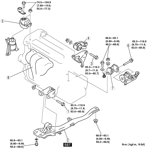
26. Remove in the order indicated in the table.
27. Install in the reverse order of removal.
28. Start the engine, and inspect and adjust the following:
atraaw00002346
|
|
1
|
No.2 engine mount through bolt
|
|
2
|
Engine mount member, No.2 engine mount rubber
|
|
3
|
No.1 engine mount through bolt
|
|
4
|
No.1 engine mount rubber
|
|
5
|
No.3 engine mount bracket
|
|
6
|
No.4 engine mount through bolt
|
|
7
|
No.4 engine mount bracket
|
|
8
|
Engine, transaxle
|
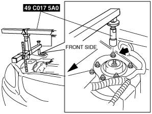
Engine Mount Member, No.2 Engine Mount Rubber Removal Note
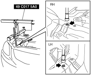
1. Install the SST using the following procedure.
atraaw00002288
|
atraaw00000060
|
atraaw00003235
|
2. Support the engine using the SST.
atraaw00002462
|
3. Remove the engine mount member and No.2 engine mount rubber.
No.3 Engine Mount Bracket Removal Note
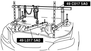
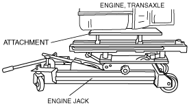
1. Secure the engine and transaxle using an engine jack and attachment.
atraaw00002348
|
2. Remove the SST.
atraaw00002462
|
No.4 Engine Mount Rubber Installation Note
1. Secure the engine and transaxle using an engine jack and attachment.
atraaw00002348
|
2. Install the No.4 engine mount bracket to the transaxle and temporarily tighten the bolts and nuts.
3. Temporarily tighten the No.4 engine mount rubber and bracket through bolt.
4. Tighten the new No.4 engine mount bracket bolts, nuts, and through bolt in the order as shown in the figure.
atraaw00002389
|
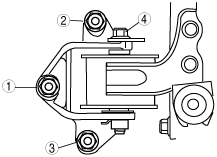
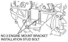
No.3 Engine Mount Bracket Installation Note
1. Tighten the No.3 engine mount bracket installation stud bolts.
atraaw00002390
|
2. Install the No.3 engine mount bracket and temporarily tighten.
3. Tighten the No.3 engine mount bracket bolt and nut in the order shown in the figure.
atraaw00002391
|
4. Install the SST using the following procedure.
atraaw00002288
|
atraaw00000060
|
atraaw00003235
|
5. Support the engine using the SST.
atraaw00002462
|
6. Remove the engine jack.
No.1 Engine Mount Rubber Installation Note
1. Install the No.1 engine mount rubber to the crossmember and temporarily tighten.
2. Tighten the No.1 engine mount through bolt.
Engine Mount Member, No.2 Engine Mount Rubber Installation Note
1. Tighten the engine mount member bolts and nut.
2. Remove the SST.
atraaw00002462
|
3. Properly tighten the No.1 engine mount rubber bolts and nut.
4. Tighten the No.2 engine mount through bolt.