|
atraaw00002142
AUTOMATIC TRANSAXLE AND TRANSFER REMOVAL/INSTALLATION[GF4AX-EL]
id051703803100
1. Disconnect the negative battery cable.
2. Drain the ATF. (See AUTOMATIC TRANSAXLE FLUID (ATF) REPLACEMENT[GF4AX-EL].)
3. Remove the following parts.
4. Remove in the order indicated in the table.
5. Install in the reverse order of removal.
6. Add ATF to the specified level. (See AUTOMATIC TRANSAXLE FLUID (ATF) REPLACEMENT[GF4AX-EL].)
7. Perform the mechanical system test and road test. (See MECHANICAL SYSTEM TEST[GF4AX-EL].) (See ROAD TEST[GF4AX-EL].)
|
Service item |
Test item |
|||
|---|---|---|---|---|
|
Line pressure test |
Stall test |
Time lag test |
Road test |
|
|
ATX replacement
|
X
|
|
|
|
|
ATX overhaul
|
X
|
X
|
X
|
X
|
|
Torque converter replacement
|
X
|
X
|
|
|
|
Oil pump replacement
|
X
|
|
|
|
|
Clutch system replacement
|
X
|
|
X
|
X
|
atraaw00002142
|
|
1
|
Selector cable
(See Selector Cable Removal Note.)
|
|
2
|
Coupler component connector
|
|
3
|
TR switch connector
|
|
4
|
GND wiring harness
|
|
5
|
Input/turbine speed sensor connector
|
|
6
|
Harness bracket
|
|
7
|
Oil dipstick and filler tube
|
|
8
|
Transaxle mounting bolt (upper side)
|
|
9
|
Starter
|
|
10
|
End plate cover
|
|
11
|
Tie-rod end ball joint
|
|
12
|
Stabilizer control link
|
|
13
|
Lower arm ball joint
|
|
14
|
Drive shaft
|
|
15
|
Joint shaft
|
|
16
|
Oil hose
|
|
17
|
Torque converter installation nuts
|
|
18
|
Transverse member
|
|
19
|
Engine mount member
|
|
20
|
No.2 engine mount rubber
|
|
21
|
No.2 engine mount bracket
|
|
22
|
No.1 engine mount rubber
|
|
23
|
No.1 engine mount bracket
|
|
24
|
No.4 engine mount bracket
|
|
25
|
Transaxle mounting bolt (lower side)
|
|
26
|
Transaxle and transfer
(See Transaxle Removal Note.)
(See Transaxle Installation Note.)
|
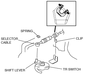
Selector Cable Removal Note
1. Remove the spring as shown in the figure.
atraaw00001836
|
2. Remove the selector cable end.
3. Press the hooks of the clips, and remove the selector cable and clips together from the bracket.
Torque Converter Nuts Removal Note
1. Using the flathead screwdriver, lock the drive plate.
atraaw00002143
|
2. Remove the torque converter nuts from the starter installation hole.
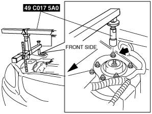
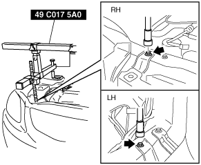
No.4 Engine Mount Bracket Removal Note
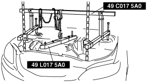
1. Install the SST using the following procedure.
atraaw00002288
|
atraaw00000060
|
atraaw00003129
|
2. Support the engine using the SST.
atraaw00002463
|
3. Remove the No.4 engine mount bracket.
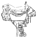
Transaxle Removal Note
1. Support the transaxle on a jack.
atraaw00002145
|
2. Remove the transaxle mounting bolts.
3. Remove the transaxle.
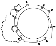
Transaxle Installation Note
1. Set the transaxle on a jack and lift it.
2. Align the drive plate installation holes by turning the torque converter.
3. Install the transaxle mounting bolts.
atraaw00002146
|
No.4 Engine Mount Bracket Installation Note
1. Install the No.4 engine mount bracket on the transaxle and temporarily tighten bolt and nut.
2. Temporarily tighten the through-bolt of No.4 engine mount rubber and bracket.
atraaw00002147
|
3. Tighten the bolt, nut and through-bolt of No.4 engine mount bracket in the order shown in the figure.
atraaw00002148
|
No.1 Engine Mount Installation Note
1. Install the No.1 engine mount bracket to the transaxle.
2. Install the No.1 engine mount rubber to the crossmember.
3. Install the through-bolt of No.1 engine mount.
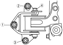
No.2 Engine Mount Installation Note
Engine Mount Member Installation Note
1. To install the engine mount member, put the stud bolts of No.2 engine mount rubber through the engine mount member installation holes.
2. Install the bolts A and nuts A as shown in the figure.
atraaw00002149
|
3. Remove the SSTs (engine support).
4. Tighten the nuts B as shown in the figure.
5. Tighten the through-bolt of No.2 engine mount.
Torque Converter Nuts Installation Note
1. Using the flathead screwdriver, lock the drive plate.
2. Tighten the torque converter mounting nuts from the starter installation hole as shown in the figure.
atraaw00002143
|
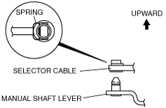
Selector Cable Installation Note
1. Install the selector lever to the manual shaft lever so that no load acts on the selector cable.
atraaw00000868
|
2. Verify that the tip of the manual shaft lever projects out of the end of the selector cable.
3. Adjust the selector cable. (See SELECTOR CABLE ADJUSTMENT.)
4. Verify that the properly installation with selector lever operation. (See SELECTOR LEVER INSPECTION.)