 |
atraaw00002010
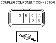
SOLENOID VALVE INSPECTION[GF4AX-EL]
id051703801900
Resistance Inspection (On‐vehicle Inspection)
1. Disconnect the negative battery cable.
2. Remove the battery tray and battery.
3. Remove the air cleaner component. (See INTAKE-AIR SYSTEM REMOVAL/INSTALLATION[L3].)
4. Disconnect the coupler component connector.
atraaw00002010
|
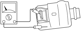
5. Measure the resistance between the following terminals.
atraaw00002011
|
ATF temperature: -40—160 °C {-40—320 °F}
|
Terminal |
Solenoid valve |
Resistance (ohm) |
|---|---|---|
|
A
|
Shift solenoid A
|
11—27
|
|
B
|
Shift solenoid B
|
11—27
|
|
C
|
Shift solenoid C
|
11—27
|
|
D
|
TCC control
|
11—27
|
|
E
|
3-2 timing
|
11—27
|
|
G
|
Pressure control
|
9—18
|
6. Connect the coupler component connector.
7. Install the air cleaner component. (See INTAKE-AIR SYSTEM REMOVAL/INSTALLATION[L3].)
8. Install the battery tray and battery.
9. Connect the negative battery cable.
Operating Inspection (On‐vehicle Inspection)
1. Disconnect the negative battery cable.
2. Remove the battery tray and battery.
3. Remove the air cleaner component. (See INTAKE-AIR SYSTEM REMOVAL/INSTALLATION[L3].)
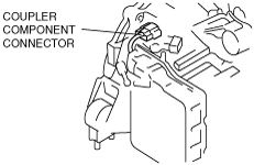
4. Disconnect the coupler component connector.
atraaw00002010
|
5. Apply battery voltage to each terminal.
atraaw00002012
|
6. Verify that each control valve operates with a “click”.
7. Connect the coupler component connector.
8. Install the air cleaner component. (See INTAKE-AIR SYSTEM REMOVAL/INSTALLATION[L3].)
9. Install the battery tray and battery.
10. Connect the negative battery cable.
Resistance Inspection (Off‐vehicle Inspection)
1. Remove the control valve body. (See CONTROL VALVE BODY REMOVAL/INSTALLATION[GF4AX-EL].)
2. Remove the solenoid valve(s).
3. Measure the resistance of each solenoid valve individually.
atraaw00002013
|
4. Install the solenoid valve(s).
5. Install the control valve body. (See CONTROL VALVE BODY REMOVAL/INSTALLATION[GF4AX-EL].)
Output Duty Inspection
Pressure control solenoid
1. Connect the (+) terminal of a dwell meter to terminal 91 at the PCM and the (-) terminal to a ground. Set the dwell meter selector to the 4 cylinder position.
2. Apply parking brake and use wheel chocks at the front and rear of the wheels.
3. Start the engine.
4. Depress the brake pedal firmly.
5. Shift the selector lever to D range.
6. Depress the accelerator pedal slowly and verify that the duty ratio charges as shown in the graph.
atraaw00002014
|