1. Disconnect the negative battery cable.
2. Remove the oil level gauge pipe.
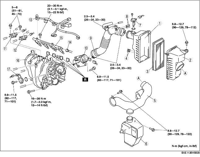
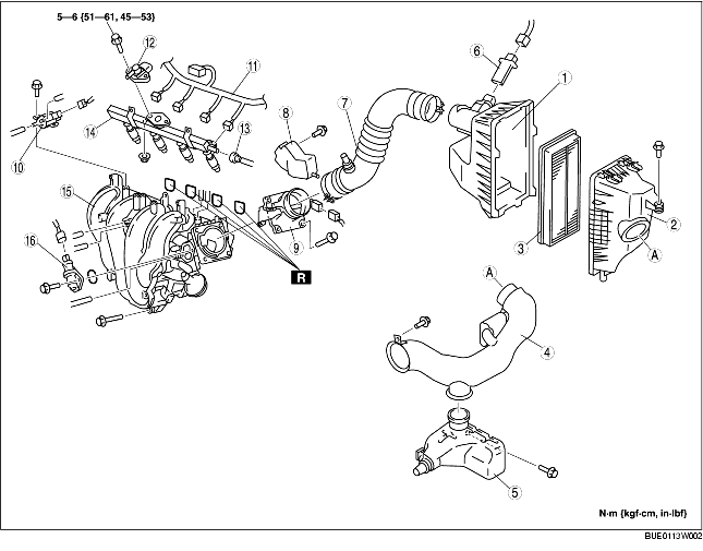
3. Remove in the order indicated in the table.
4. Install in the reverse order of removal.
R.H.D. model
|
1
|
Air cleaner cover
|
|
2
|
Air cleaner case
|
|
3
|
Air cleaner element
|
|
4
|
Vacuum hose (catch tank area)
|
|
5
|
Fresh-air duct
(See Fresh-Air Duct Removal Note.)
|
|
6
|
Resonance chamber
|
|
7
|
MAF sensor
|
|
8
|
Vacuum hose ( purge solenoid valve area)
|
|
9
|
Air hose
|
|
10
|
Throttle body
|
|
11
|
Variable intake air solenoid valve
|
|
12
|
Variable tumble solenoid valve
|
|
13
|
Wiring harness
|
|
14
|
Quick release connector
|
|
15
|
Fuel distributor
|
|
16
|
Intake manifold
(See Intake Manifold Removal Note.)
|
|
17
|
IAC valve
|
L.H.D. model
|
1
|
Air cleaner cover
|
|
2
|
Air cleaner case
|
|
3
|
Air cleaner element
|
|
4
|
Fresh-air duct
(See Fresh-Air Duct Removal Note.)
|
|
5
|
Resonance chamber
|
|
6
|
MAF sensor
|
|
7
|
Air hose
|
|
8
|
Throttle body cover
|
|
9
|
Throttle body
|
|
10
|
Variable intake air solenoid valve
|
|
11
|
Wiring harness
|
|
12
|
Fuel temperature/fuel pressure sensor
|
|
13
|
Quick release connector
|
|
14
|
Fuel distributor
|
|
15
|
Intake manifold
(See Intake Manifold Removal Note.)
|
|
16
|
IAC valve
|
1. Before removing the fresh-air duct, remove the battery and battery tray. (See BATTERY REMOVAL/INSTALLATION [L3, AJ (3.0L Duratec)].)
1. Before removing the resonance chamber, remove the front tire (LH) and the front side mud guard.
1. Remove the fan component using the following procedure.
2. Remove the intake manifold.
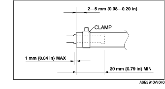
1. Install the vacuum hose and clamps as shown in the figure.
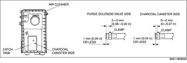
1. Install the vacuum hose and clamps as shown in the figure.