|
STEP
|
INSPECTION
|
ACTION
|
|
|---|---|---|---|
|
1
|
INSPECT FOR DTCs IN ABS HU/CM
• Have DTCs been stored in memory?
|
Yes
|
Perform the applicable DTC inspection.
(See DTC Table.)
|
|
No
|
Inspect the instrument cluster.
If the instrument cluster is normal, inspect CAN communication.
If instrument cluster has a malfunction, go to the next step.
|
||
|
2
|
VERIFY WHETHER MALFUNCTION IS IN WARNING LIGHTS AND INDICATOR LIGHT'S COMMON POWER SUPPLY, OR IN OTHER WARNING LIGHTS AND INDICATOR LIGHTS
• Do other warning and indicator lights illuminate when the ignition switch is turned to the ON position?
|
Yes
|
Replace the instrument cluster. (open circuit in instrument cluster)
|
|
No
|
Go to the next step.
|
||
|
3
|
INSPECT INSTRUMENT CLUSTER POWER SUPPLY FUSE
• Is the instrument cluster ignition power supply fuse normal?
|
Yes
|
Go to the next step.
|
|
No
|
Inspect for a short to ground on circuit of blown fuse.
Repair or replace if necessary.
Install appropriate amperage fuse.
|
||
|
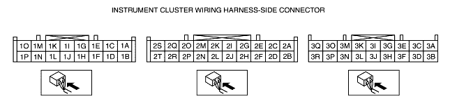
*4 |
VERIFY WHETHER MALFUNCTION IS IN WIRING HARNESS (BETWEEN INSTRUMENT CLUSTER POWER SUPPLY AND INSTRUMENT CLUSTER FOR CONTINUITY) OR INSTRUMENT CLUSTER
• Turn the ignition switch to the ON position.
• Measure voltage at instrument cluster connector terminal 3O.
• Is the voltage approx. 12 V?
|
Yes
|
Replace the instrument cluster (open circuit in instrument cluster).
|
|
No
|
Inspect for open circuit in wiring harness between the instrument cluster and ground.
Repair or replace if necessary.
Replace the ABS HU/CM.
(See ABS HU REMOVAL/INSTALLATION.)
|
||
|
|
|||