ON-BOARD DIAGNOSIS [L3]
id0402008055a1
On-Board Diagnostic (OBD) Test Description
• The OBD test inspects the integrity and function of the ABS and outputs the results when requested by the specific tests.
• On-board diagnostic test also:
-
- Provides a quick inspection of the ABS usually performed at the start of each diagnostic procedure.
-
- Provides verification after repairs to ensure that no other faults occurred during service.
• The OBD test is divided into 3 tests:
-
- Read/clear diagnostic results, PID monitor and record and active command modes.
Read/clear diagnostic results
-
• This function allows you to read or clear DTCs in the ABS HU/CM memory.
PID/Data monitor and record
-
• This function allows you to access certain data values, input signals, calculated values, and system status information.
Active command modes
-
• This function allows you to control devices through the WDS or equivalent.
Reading DTCs Procedure
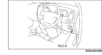
1. Connect the WDS or equivalent to the vehicle DLC-2 connector.
2. Retrieve DTC using the WDS or equivalent.
Clearing DTCs Procedures
1. After repairs have been made, perform the DTCs reading procedure.
2. Erase DTC using the WDS or equivalent.
3. Ensure that the customer's concern has been resolved.
PID/Data Monitor and Record Procedure
1. Connect the WDS or equivalent to the vehicle DLC-2 connector.
2. Access and monitor PIDs using the WDS or equivalent.
Active Command Modes Procedure
1. Connect the WDS or equivalent to the vehicle DLC-2 16-pin connector.
2. Turn the ignition switch to the ON position (engine off) or start the engine.
3. Activate active command modes using the WDS or equivalent.
DTC Table
|
DTC
|
System Malfunction Location
|
Page
|
|
WDS or equivalent display
|
|
B1342
|
ABS HU/CM
|
|
|
B1676
|
Power supply system
|
|
|
B2477
|
ABS HU/CM configuration system
|
|
|
B2900
|
PCM communication
|
|
|
C1095
|
Pump motor, motor relay
|
|
|
C1145
|
RF ABS wheel-speed sensor
|
|
|
C1155
|
LF ABS wheel-speed sensor
|
|
C1165
|
RR ABS wheel-speed sensor
|
|
C1175
|
LR ABS wheel-speed sensor
|
|
C1233
|
LF ABS sensor rotor
|
|
|
C1234
|
RF ABS sensor rotor
|
|
C1235
|
RR ABS sensor rotor
|
|
C1236
|
LR ABS sensor rotor
|
|
C1730*
|
G-sensor
|
|
|
C1805
|
PCM communication
|
|
|
C2769*
|
G-sensor
|
|
|
C2770*
|
G-sensor
|
|
|
U1900
|
CAN line
|
|
|
U2023
|
CAN line
|
-
* :
4WD vehicles
PID/DATA Monitor Table
|
PID name (definition)
|
Unit/Operation
|
Operation Status (Reference)
|
Action
|
ABS HU/CM
Terminal
|
|
WDS or equivalent display
|
|
ABSLF_I
|
On/Off
|
• Solenoid valve activated: On
• Solenoid valve not activated: Off
|
• Inspect the ABS HU/CM.
|
-
|
|
ABSLF_O
|
On/Off
|
• Solenoid valve activated: On
• Solenoid valve not activated: Off
|
• Inspect the ABS HU/CM.
|
-
|
|
ABSLR_I
|
On/Off
|
• Solenoid valve activated: On
• Solenoid valve not activated: Off
|
• Inspect the ABS HU/CM.
|
-
|
|
ABSLR_O
|
On/Off
|
• Solenoid valve activated: On
• Solenoid valve not activated: Off
|
• Inspect the ABS HU/CM.
|
-
|
|
ABSRF_I
|
On/Off
|
• Solenoid valve activated: On
• Solenoid valve not activated: Off
|
• Inspect the ABS HU/CM.
|
-
|
|
ABSRF_O
|
On/Off
|
• Solenoid valve activated: On
• Solenoid valve not activated: Off
|
• Inspect the ABS HU/CM.
|
-
|
|
ABSRR_I
|
On/Off
|
• Solenoid valve activated: On
• Solenoid valve not activated: Off
|
• Inspect the ABS HU/CM.
|
-
|
|
ABSRR_O
|
On/Off
|
• Solenoid valve activated: On
• Solenoid valve not activated: Off
|
• Inspect the ABS HU/CM.
|
-
|
|
BOO_ABS
|
On/Off
|
• Brake pedal depressed: On
• Brake pedal released: Off
|
• Inspect the brake switch.
|
-
|
|
BRK_FLUID
|
OK/Low
|
• Brake fluid level at LOW level or more: OK
• Brake fluid level less than LOW level: Off
|
• Inspect the brake fluid level.
• Inspect the brake fluid level sensor.
|
-
|
|
CCNTABS
|
-
|
• DTC detected: 1-255
• No DTCs detected: 0
|
• Perform the DTC inspection.
|
-
|
|
LAT_ACCL
|
G
|
• Stopped or low vehicle speed: 0 G
• Acceleration: Changes to 0 G-positive
• Deceleration: Changes to 0 G-negative
|
• Inspect the ABS HU/CM.
|
-
|
|
LF_WSPD
|
km/h, MPH
|
• Vehicle stopped: 0 km/h, 0 MPH
• Vehicle driven: Vehicle speed
|
• Inspect the ABS wheel-speed sensor.
|
I, F
|
|
LR_WSPD
|
km/h, MPH
|
• Vehicle stopped: 0 km/h, 0 MPH
• Vehicle driven: Vehicle speed
|
• Inspect the ABS wheel-speed sensor.
|
AJ, AG
|
|
RF_WSPD
|
km/h, MPH
|
• Vehicle stopped: 0 km/h, 0 MPH
• Vehicle driven: Vehicle speed
|
• Inspect the ABS wheel-speed sensor.
|
AP, AS
|
|
RR_WSPD
|
km/h, MPH
|
• Vehicle stopped: 0 km/h, 0 MPH
• Vehicle driven: Vehicle speed
|
• Inspect the ABS wheel-speed sensor.
|
O, R
|
Active Command Modes Table
|
Command name
|
Output device
|
Operation
|
Operating condition
|
|
LF_INLET
|
LF inlet solenoid valve
|
On/Off
|
Ignition switch at ON
|
|
LF_OUTLET
|
LF outlet solenoid valve
|
|
LR_INLET
|
LR inlet solenoid valve
|
|
LR_OUTLET
|
LR outlet solenoid valve
|
|
PMP_MOTOR
|
Pump motor
|
|
RF_INLET
|
RF inlet solenoid valve
|
|
RF_OUTLET
|
RF outlet solenoid valve
|
|
RR_INLET
|
RR inlet solenoid valve
|
|
RR_OUTLET
|
RR outlet solenoid valve
|