Diagnostic procedure
|
STEP
|
INSPECTION
|
ACTION
|
|
|---|---|---|---|
|
1
|
VERIFY FREEZE FRAME DATA HAS BEEN RECORDED
• Has the FREEZE FRAME DATA been recorded?
|
Yes
|
Go to the next step.
|
|
No
|
Record the FREEZE FRAME DATA on the repair order, then go to the next step.
|
||
|
2
|
VERIFY RELATED REPAIR INFORMATION AVAILABILITY
• Verify related Service Bulletins and or/on-line repair information availability.
• Is any related repair information available?
|
Yes
|
Perform repair or diagnosis according to the available repair information.
• If the vehicle is not repaired, go to the next step.
|
|
No
|
Go to the next step.
|
||
|
3
|
VERIFY CURRENT INPUT SIGNAL STATUS: IS CONCERN INTERMITTENT OR CONSTANT
• Turn the ignition switch to the ON position (engine off).
• Access TFTV PID using the WDS or equivalent.
• Are PID readings within 0.2-4.9 V?
|
Yes
|
Go to the intermittent concern troubleshooting procedure, then go to Step 16.
|
|
No
|
Voltage 0.1 V or less: Go to Step 11.
Voltage 4.9 V or more: Go to the next step.
|
||
|
4
|
INSPECT SOLENOID VALVE CONNECTOR FOR POOR CONNECTION
• Turn the ignition switch to the LOCK position.
• Disconnect the solenoid valve connector.
• Inspect for poor connection (such as damaged/pulled-out pins, corrosion)
• Is the connection normal?
|
Yes
|
Go to the next step.
|
|
No
|
Repair or replace connector and/or terminal, then go to Step 16.
|
||
|
5
|
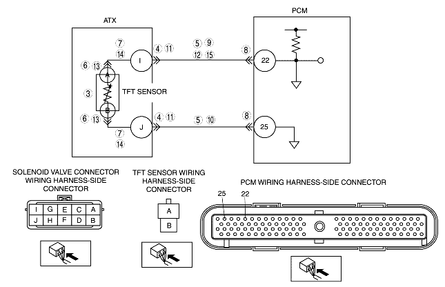
INSPECT TFT SENSOR CIRCUIT
• Turn the ignition switch to the ON position (engine off).
• Access TFTV PID using the WDS or equivalent.
• Connect between solenoid valve connector terminals I and J (wiring harness-side) using jumper wire.
• Verify if TFTV PID changes to 0.2 V or less.
• Does TFTV PID change?
|
Yes
|
Go to the next step.
|
|
No
|
Go to Step 8.
|
||
|
6
|
INSPECT TFT SENSOR CONNECTOR FOR POOR CONNECTION
• Turn the ignition switch to the LOCK position.
• Remove the valve body cover.
• Disconnect TFT sensor connector.
• Inspect for poor connection (such as damaged/pulled-out pins, corrosion).
• Is the connection normal?
|
Yes
|
Go to the next step.
|
|
No
|
Repair the terminals or replace the TFT sensor, then go to Step 16.
|
||
|
7
|
INSPECT TFT SENSOR CIRCUIT FOR OPEN CIRCUIT
• Inspect for continuity between TFT sensor terminals (wiring harness-side) and solenoid valve connector terminals (transaxle case side).
• Is there continuity?
|
Yes
|
Replace the TFT sensor, then go to Step 16.
|
|
No
|
Repair or replace the wiring harness, then go to Step 16.
|
||
|
8
|
INSPECT PCM CONNECTOR FOR POOR CONNECTION
• Turn the ignition switch to the LOCK position.
• Disconnect the PCM connector.
• Inspect for poor connection (such as damaged/pulled-out pins, corrosion).
• Is the connection normal?
|
Yes
|
Go to the next step.
|
|
No
|
Repair the terminals, then go to Step 16.
|
||
|
9
|
INSPECT WIRING HARNESS FOR OPEN CIRCUIT
• Disconnect the solenoid valve connector.
• Connect the PCM connector.
• Turn the ignition switch to the ON position (engine off).
• Inspect the voltage at solenoid valve connector terminal I (wiring harness-side).
• Is the voltage 5 V?
|
Yes
|
Go to the next step.
|
|
No
|
Repair or replace the wiring harness, then go to Step 16.
|
||
|
10
|
INSPECT SOLENOID VALVE CONNECTOR CIRCUIT FOR OPEN CIRCUIT
• Turn the ignition switch to the LOCK position.
• Inspect for continuity between solenoid valve connector terminal J (wiring harness-side) and body ground.
• Is there continuity?
|
Yes
|
Go to Step 16.
|
|
No
|
Repair or replace the wiring harness, then go to Step 16.
|
||
|
11
|
INSPECT TERMINAL CONDITION
• Turn the ignition switch to the LOCK position.
• Disconnect the solenoid valve connector.
• Inspect for poor connection (such as damaged/pulled-out pins, corrosion).
• Is there any malfunction?
|
Yes
|
Repair or replace terminals, then go to Step 16.
• If terminals cannot be repaired, replace harness, then go to Step 16.
|
|
No
|
Go to the next step.
|
||
|
12
|
INSPECT TFT SENSOR CIRCUIT
• Turn the ignition switch to the ON position (engine off).
• Verify if TFTV PID changes to 4.9 V or more when solenoid valve connector is disconnected.
• Does TFTV PID change?
|
Yes
|
Go to the next step.
|
|
No
|
Go to Step 16.
|
||
|
13
|
INSPECT TFT SENSOR TERMINALS CONDITION
• Turn the ignition switch to the LOCK position.
• Disconnect TFT sensor connector.
• Inspect for bent TFT sensor terminals.
• Is there any malfunction?
|
Yes
|
Repair the terminals or replace the TFT sensor, then go to Step 16.
|
|
No
|
Go to the next step.
|
||
|
14
|
INSPECT TFT SENSOR CIRCUIT FOR SHORT TO GROUND
• Inspect continuity between TFT sensor terminals (wiring harness-side) and body ground.
• Is there continuity?
|
Yes
|
Repair or replace the wiring harness, then go to Step 16.
|
|
No
|
Go to the next step.
|
||
|
15
|
INSPECT SOLENOID VALVE CONNECTOR CIRCUIT FOR SHORT TO GROUND
• Turn the ignition switch to the LOCK position.
• Inspect for continuity between solenoid valve connector terminal I (wiring harness-side) and body ground.
• Is there continuity?
|
Yes
|
Repair or replace the wiring harness, then go to the next step.
|
|
No
|
Replace the TFT sensor, then go to the next step.
|
||
|
16
|
VERIFY TROUBLESHOOTING OF DTC P0710 COMPLETED
• Make sure to reconnect all the disconnected connectors.
• Clear the DTC from memory using the WDS or equivalent.
• Drive the vehicle under following condition for 100 s or more.
• Are any DTCs present?
|
Yes
|
Replace the PCM, then go to the next step.
|
|
No
|
Go to the next step.
|
||
|
17
|
VERIFY AFTER REPAIR PROCEDURE
• Perform the "After Repair Procedure".
• Are any DTCs present?
|
Yes
|
Go to the applicable DTC inspection.
(See DTC TABLE [GF4AX-EL].)
|
|
No
|
DTC troubleshooting completed.
|
||