MANUAL TRANSAXLE REMOVAL/INSTALLATION [G15M-R, G25MX-R]
id0515a6800600
Removal
1. Remove the battery tray. (See BATTERY REMOVAL/INSTALLATION [YF (2.0L Zetec)].)
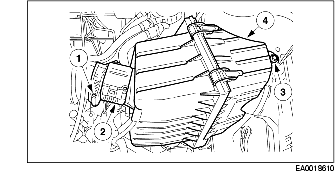
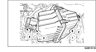
2. Remove the air cleaner housing.
-
(1) Loosen the air cleaner outlet tube clamp.
-
(2) Disconnect the MAF sensor connector.
-
(3) Remove the air cleaner housing bolt.
-
(4) Remove the air cleaner housing.
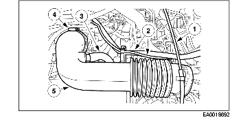
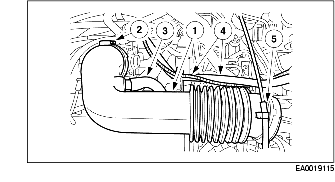
3. Remove the air cleaner outlet tube.
-
(1) Disconnect the accelerator cable from the air cleaner outlet tube.
-
(2) Disconnect the emission management tube and hose.
-
(3) Disconnect the crankcase ventilation hose.
-
(4) Loosen the air cleaner outlet tube clamp.
-
(5) Remove the air cleaner outlet tube.
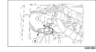
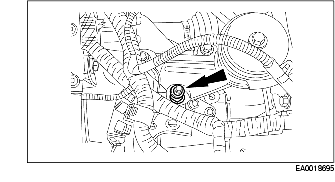
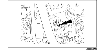
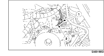
4. Disconnect the back-up light switch connector.
-
(1) Disconnect the connector from the front wiring harness bracket.
-
(2) Disconnect the back-up light switch connector.
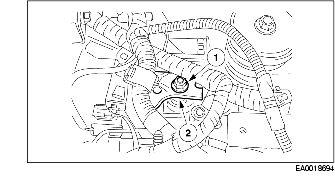
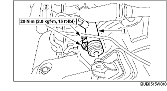
5. Position the front wiring harness bracket aside.
-
(1) Remove the nut.
-
(2) Position the front wiring harness bracket aside.
6. Remove the front wiring harness bracket spacer.
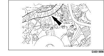
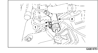
7. Disconnect the wiring harness from the rear wiring harness bracket.
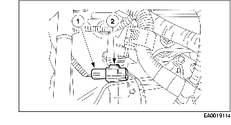
8. Disconnect the neutral switch connector.
-
(1) Disconnect the connector from the rear wiring harness bracket.
-
(2) Disconnect the neutral switch connector.
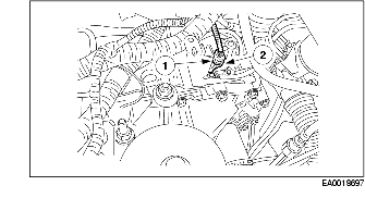
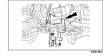
9. Position the rear wiring harness bracket aside.
-
(1) Remove the bolts.
-
(2) Position the rear wiring harness bracket aside.
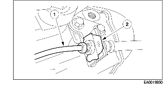
10. Disconnect the vehicle speed sensor connector.
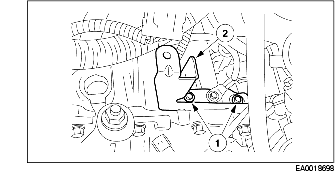
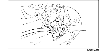
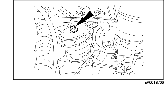
11. Disconnect the clutch release cylinder line from the bracket.
-
(1) Remove the clip.
-
(2) Disconnect the clutch release cylinder line from the bracket.
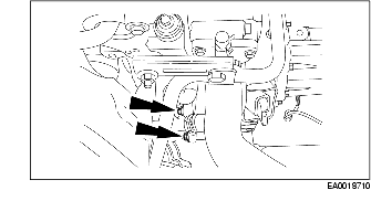
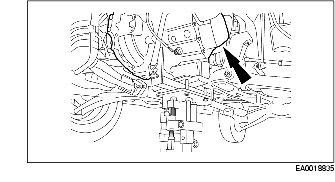
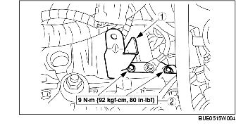
12. Position the clutch release cylinder aside.
-
(1) Remove the bolts.
-
(2) Position the clutch release cylinder aside.
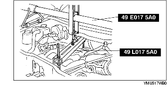
13. Using the SSTs, support the engine.
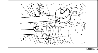
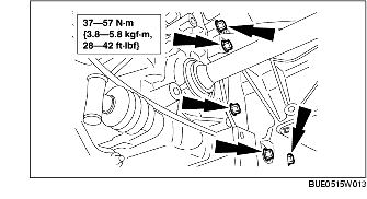
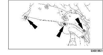
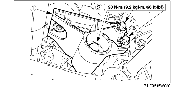
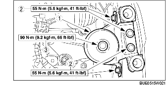
14. Remove the No.4 engine mount rubber.
-
(1) Remove the five bolts.
-
(2) Remove the No.4 engine mount rubber.
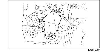
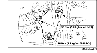
15. Remove the No.4 engine mount bracket.
-
(1) Remove the nuts and the bolt.
-
(2) Remove the No.4 engine mount bracket.
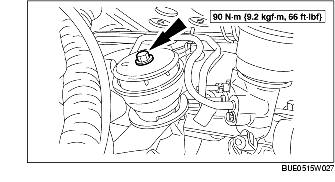
16. Remove the No.1 engine mount rubber through bolt.
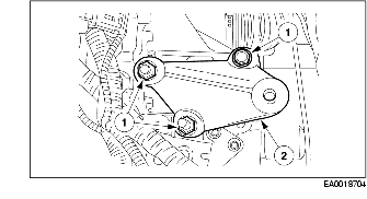
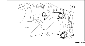
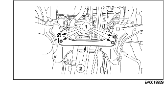
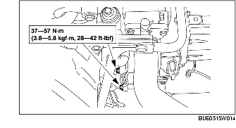
17. Remove the No.2 engine mount bracket.
-
(1) Remove the five bolts.
-
(2) Remove the No.2 engine mount bracket.
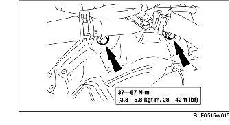
18. Position the starter aside.
-
(1) Remove the bolts.
-
(2) Position the starter aside.
19. Remove the top transaxle mounting bolts.
20. Remove the front transaxle mounting bolts.
21. Remove the transfer case. (4WD) (See TRANSFER REMOVAL/INSTALLATION [G25MX-R].)
22. Remove the front drive shaft (LH). (See FRONT DRIVE SHAFT REMOVAL/INSTALLATION.)
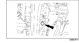
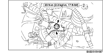
23. Drain the transaxle oil.
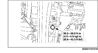
24. Install the drain plug.
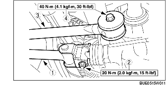
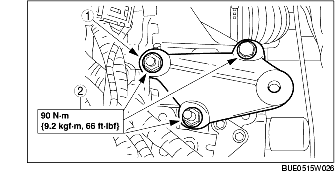
25. Remove the No.1 engine mount bracket.
-
(1) Remove the bolts.
-
(2) Remove the No.1 engine mount bracket.
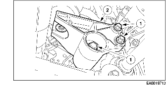
26. Disconnect the change control rod and extension bar. (2WD)
-
(1) Remove the bolt.
-
(2) Position the extension bar aside.
-
(3) Remove the bolt and nut.
-
(4) Position the change control rod aside.
27. Disconnect the shift and select cable. (4WD) (See SHIFT MECHANISM REMOVAL/INSTALLATION [G25MX-R].)
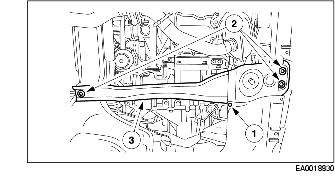
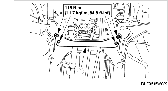
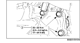
28. Remove the transverse member.
-
(1) Remove the bolts.
-
(2) Remove the transverse member.
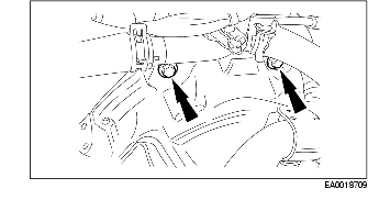
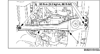
29. Remove the engine mount member.
-
(1) Remove the splash shield screw.
-
(2) Remove the bolts and the nut.
-
(3) Remove the engine mount member.
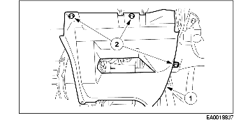
30. Remove the LH side splash shield screws and the push pin-type retainer.
31. Remove the LH side splash shield.
-
(1) Remove the screws.
-
(2) Remove the LH side splash shield.
32. Support the transaxle.
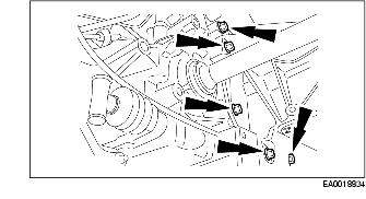
33. Remove the seven transaxle mounting bolts.
-
Note
-
• 2WD only shown, 4WD similar.
34. Remove the transaxle.
-
• Separate the drive shaft (RH) from the transaxle before lowering transaxle.
Installation
1. Apply a thin coating of grease to the spline of the input shaft.
2. Secure the transaxle on a transmission jack. Raise the transaxle to the correct height and position the transaxle to the engine.
-
Note
-
• On 2WD only vehicles, make sure to align the drive shaft (RH) with the transaxle.
3. Install the seven transaxle mounting bolts.
4. Remove the transaxle support.
5. Install the LH side splash shield.
-
(1) Position the LH side splash shield.
-
(2) Install the screws.
6. Install the LH side splash shield screws and the pin-type retainer.
7. Install the engine mount member.
-
(1) Position the engine mount member.
-
(2) Install the bolts and the nut.
-
(3) Install the splash shield screw.
8. Install the transverse member.
-
(1) Position the transverse member.
-
(2) Install the bolts.
9. Connect the shift and select cable. (4WD) (See SHIFT MECHANISM REMOVAL/INSTALLATION [G25MX-R].)
10. Connect the change control rod and extension bar. (2WD)
-
(1) Position the change control rod.
-
(2) Install the bolt and nut.
-
(3) Position the extension bar.
-
(4) Install the bolt.
11. Install the No.1 engine mount bracket.
-
(1) Position the No.1 engine mount bracket.
-
(2) Install the bolts.
12. Install the front drive shaft (LH). (See FRONT DRIVE SHAFT REMOVAL/INSTALLATION.)
13. Install the transfer case. (4WD) (See TRANSFER REMOVAL/INSTALLATION [G25MX-R].)
14. Install the front transaxle mounting bolts.
15. Install the top transaxle mounting bolts.
16. Install the starter.
-
(1) Position the starter.
-
(2) Position the connector.
-
(3) Install the bolts.
17. Install the No.2 engine mount bracket.
-
(1) Position the No.2 engine mount bracket.
-
(2) Install the four bolts.
-
(3) Install the bolt.
18. Install the No.1 engine mount through bolt.
19. Install the No.4 engine mount bracket.
-
(1) Position the No.4 engine mount bracket.
-
(2) Install the nuts and the bolt.
20. Install the No.4 engine mount rubber.
-
(1) Position the No.4 engine mount rubber.
-
(2) Install the bolts.
-
(3) Install the No.4 engine mount rubber to bracket through bolt.
21. Remove the SST.
22. Install the clutch release cylinder.
-
(1) Position the clutch release cylinder.
-
(2) Install the bolts.
23. Attach the clutch release cylinder line to the bracket.
-
(1) Attach the clutch release cylinder line to the bracket.
-
(2) Install the clip.
24. Connect the vehicle speed sensor connector.
25. Install the rear wiring harness bracket.
-
(1) Position the rear wiring harness bracket.
-
(2) Install the bolts.
26. Connect the neutral switch connector.
-
(1) Connect the neutral switch connector.
-
(2) Attach the switch connector to the rear wiring harness bracket.
27. Attach the wiring harness to the rear wiring harness bracket.
28. Install the front wiring harness bracket spacer.
29. Install the front wiring harness bracket.
-
(1) Position the front wiring harness bracket.
-
(2) Install the nut.
30. Connect the back-up light switch connector.
-
(1) Connect the back-up light switch connector.
-
(2) Attach the connector to the front wiring harness bracket.
31. Install the air cleaner outlet tube.
-
(1) Position the air cleaner outlet tube.
-
(2) Tighten the air cleaner outlet tube clamp.
-
(3) Connect the crankcase ventilation hose.
-
(4) Attach the emission management tube and hose.
-
(5) Attach the accelerator cable to the air cleaner outlet tube.
32. Install the air cleaner housing.
-
(1) Position the air cleaner housing.
-
(2) Install the air cleaner housing bolt.
-
(3) Connect the MAF sensor connector.
-
(4) Tighten the air cleaner outlet tube clamp.
33. Install the battery tray. (See BATTERY REMOVAL/INSTALLATION [YF (2.0L Zetec)].)
34. Fill the transaxle oil. (See MANUAL TRANSAXLE OIL REPLACEMENT [G15M-R, G25MX-R].)