1. Clean the transaxle exterior thoroughly with a steam cleaner or cleaning solvents.
2. Disconnect the negative battery cable.
3. Remove the battery and battery tray.
4. Remove the air cleaner component. (See INTAKE-AIR SYSTEM REMOVAL/INSTALLATION [L3].)
5. Remove the splash shield.
6. Remove the under cover.
7. Drain the ATF. (See AUTOMATIC TRANSAXLE FLUID (ATF) REPLACEMENT [GF4AX-EL].)
8. Remove the oil cooler hose. (See OIL COOLER REMOVAL/INSTALLATION [GF4AX-EL].)
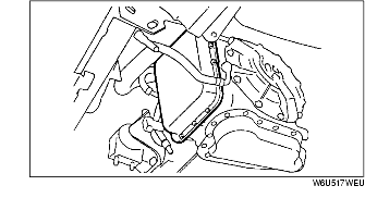
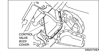
9. Remove the control valve body cover.
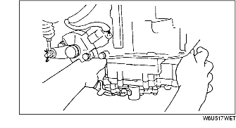
10. Disconnect the solenoid valve connectors and TFT sensor connector.
11. Remove the control valve body component.
1. Align the manual plate and the manual valve.
2. Install the control valve body component.
3. Match the harness colors and connect the solenoid connectors and TFT sensor connector.
4. Apply a light coat of silicon sealant to the contact surfaces of the oil pan and transaxle case.
5. Install the control valve body cover.
6. Install the oil cooler hose. (See OIL COOLER REMOVAL/INSTALLATION [GF4AX-EL].)
7. Install the under cover.
8. Install the splash shield.
9. Install the air cleaner component. (See INTAKE-AIR SYSTEM REMOVAL/INSTALLATION [L3].)
10. Install the battery tray and battery.
11. Connect the negative battery cable.
12. Add ATF to the specified level. (See AUTOMATIC TRANSAXLE FLUID (ATF) REPLACEMENT [GF4AX-EL].)
13. Inspect for leakage of ATF from the control valve body cover or the oil hose connecting points.
14. Perform the mechanical system test. (See MECHANICAL SYSTEM TEST [GF4AX-EL].)